Using firmware for efficiency in battery-powered devices
Processors have many different power modes depending on what is required
Battery powered products are commonplace today. Whether it’s a pace maker, smoke detector, cell phone, or high-end computing device, battery life is a big concern. Electronic hardware has evolved to handle these low power needs. Processors have many different power modes depending on what is required. And RF transceiver chips have different power needs depending on whether it’s waiting for a signal, sending a signal, or receiving a signal.
For devices that are powered by the ac line, firmware can be written that is somewhat wasteful of power. For example, the firmware has the luxury of using infinite loops. These loops may perform repetitive tasks to wait for some condition to occur. Loops may implement a clock function that causes a subroutine to be called every minute. Conversely, devices that are powered from batteries must employ techniques in firmware to maximize battery runtime. This firmware must avoid these loops due to processor power needs. The proper technique is to put the processor in a low power idle mode and have timer interrupts wake the processor when it needs to do something. Repetitive tasks need to be triggered with a timer that undertake the action and then put the processor back in a low power idle mode.
Peripheral management
Another technique used by developers of ac-powered devices is to turn on all peripheral chips at boot up and leave them in normal mode indefinitely. This simplifies the firmware but causes higher than needed power consumption. Like the processor, peripheral chips should be kept at the lowest power state possible. RF transceiver chips use a lot of power when transmitting and receiving signals, but can use less power waiting for a signal if in the proper state.
Low power RF transceiver chips have the capability to “Wake On Radio”. For example, Intel’s CC2500 RF transceiver uses 1.5mA when in idle mode. In sleep mode where Wake On Radio is used, it uses 900 nA. This is a difference greater than three orders of magnitude, so it is important to put the radio to sleep rather than letting it maintain a power consuming idle state. Thus, to optimize power consumption requires more complex firmware that actively manages peripheral chip power states.
Debugging tools must also be improved when developing low power applications. Cross-compilers and debuggers do a good job providing insight into functional defects, but are inadequate at identifying power usage defects. Debuggers don’t provide insight that a RF transceiver chip has been left on, or whether a processor has been left in the wrong power mode, or if a timer interrupt is consuming too much power. To understand total power consumption, another debugging tool must be used: A DC Power Analyzer.
A DC Power Analyzer provides the developer with a visualization of power consumption as the device runs. To illustrate the DC Power Analyzer’s effectiveness, consider a capability many battery powered products implement: product Self-test. If Self-test has to put an RF transceiver in idle mode to run a test but forgets to put it back into sleep mode after the test, battery life will be adversely affected. These programming defects are difficult to identify. DC Power Analyzers assist a developer by clearly showing power usage before and after Self-test has executed. A quick glance at a power consumption vs time will clearly show the problem, as the device will be consuming almost 1.5 mA extra after Self-test is completed.
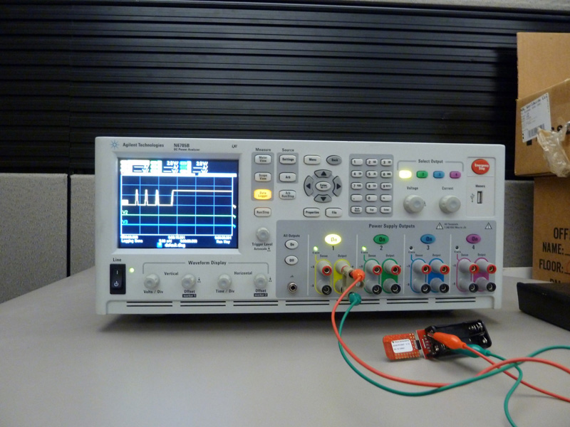
To demonstrate how to detect excessive power usage, we used the Agilent N6705B DC Power Analyzer along with the Agilent 14585A Control and Analysis Software. The test setup is shown below (see Figure 1). First, a simple program was developed to execute on the Intel MSP430 processor, which supports five low power modes. Acting as a peripheral chip to the MSP430, the Intel CC2500 RF transceiver supports a wide range of configurations, including Wake On Radio.
Click image to enlarge
Figure 1: Test setup to measure power consumption of MSP430 processor and CC2500 RF transceiver.
Once everything is connected, we started Agilent's 14585 Control and Analysis Software and hit the power on button for channel 1. We allowed the instrument and software to collect current data for approximately one minute. The software showed power usage as the MSP430 program executes our program (see Figure 2).
Click image to enlarge
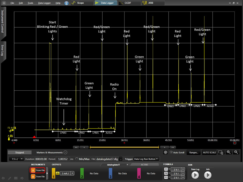
Figure 2: The waveform shows current consumption vs time for the functioning MSP430 processor and CC2500 RF transceiver.
The executing program begins by flashing two LEDS to indicate program execution has begun. This flashing can be seen approximately 5 seconds into the chart. From there, the processor is put into low power mode 3 for approximately 4.5 seconds and then low power mode 2 for another 4.5 seconds. This power mode change is done by a watchdog timer event that wakes up every 1.5 seconds. The short regular blips in the chart show the watchdog timer executing its programmed logic. Throughout the 1 minute program the watchdog timer will cause a change to a different power mode every 4.5 seconds. These power mode changes are marked by flashing LEDs that are clearly seen in the chart.
For most power modes the watchdog timer events are very easy to detect. They can be seen as small power spikes approximately 1.5 seconds apart. At 23 seconds, the watchdog timer spikes disappear. This is due to the processor being put in active mode, which is the mode interrupts, such as the watchdog timer, execute. At 27 seconds the watchdog timer spikes reappear as a result of the processor being put back into a low power mode.
At approximately 28 seconds into the test, the RF transceiver is put into idle mode. This causes the current to rise significantly; from 1 μA to 1.5 mA. Although this is a change of 1000 times, or three orders of magnitude, events such as the watchdog timer can still be seen, thanks to the wide dynamic range for measuring current provided by the Agilent N6705B DC Power Analyzer. This allows the user to see important details whether the system is drawing microamps or milliamps or even amperes of current. With this tool, the developer can determine power modes of both chips, even though one chip uses much more power.
The insight this chart provides allows developers to verify program correctness that is not possible with traditional debugging and test tools. DC Power Analyzers allow users to identify what power mode a processor is in, the frequency and duration of timer events, and when peripherals chips are turned on and off. They can also measure total power usage over a period of time so battery life can be accurately predicted. An interesting observation with this chart is the high power usage of the LED’s. This reminds us that that lighting up LED’s should be limited for power-conscious applications.
In Figure 3, the markers help us to see the power mode in which the processor is running. After zooming in on the chart, the markers allowed us to make an average current measurement between two watchdog timer events. The average current between the two markers in 453 nA. This measurement confirms that the MSP430 is in low power mode 3.

Click image to enlarge
Figure 3: Another screenshot of the Agilent 14585A Control and Analysis Software.
Measurements can also be made that include the watchdog timer events. This allows a user to compare battery life versus watchdog timer frequency. This particular example has the watchdog timer executing every 1.5 seconds. The program can be rerun with the watchdog timer occurring every 0.5 seconds. The ratio between these measurements would provide the developer insight into how increasing watchdog timer frequency will affect battery life. This is beneficial information when one is trying to maximize battery life.
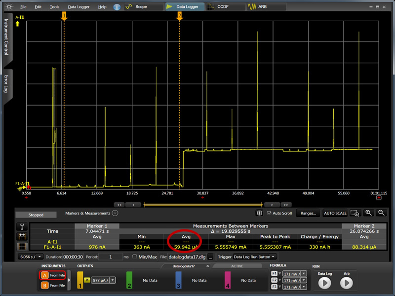
Another battery life question a firmware developer will need to answer is how long will the product run on a set of batteries. The Agilent 14585A Control and Analysis Software can also be used to determine overall battery runtime (see Figure 4). The first measurement uses two markers to measure the average current usage while the RF transceiver chip is off. The average current usage is approximate 60 μA over a period of one second. Assuming the product uses two standard AA batteries that are rated at 2400mAH, we would expect the product to run for 9 years in these low power modes.
Click image to enlarge
Figure 4: The Agilent 14585A Control and Analysis Software can be used to determine battery runtime.
If we move the markers so they measure the power usage while the RF transceiver is in idle mode we find it uses an average of 1.7 mA over a period of one second. This translates to a battery life of 117 days. If we put the RF transceiver into sleep mode and used Wake On Radio rather than idle mode, battery life could have been extended to 3 years and still have been able to respond to incoming signals. This emphasizes the importance of Wake On Radio.
When a firmware developer is tasked with developing a battery-powered product, they need to aware that the firmware may need to change considerably to insure the product has acceptable battery life. Important guidelines to keep in mind are:
• Avoid loops and use interrupts to launch program logic. Interrupt timers are a good way to launch repetitive logic.
• Always keep the processor and peripheral chips in the lowest acceptable power state. For chips such as RF transceivers, use the Wake On Radio capability when the product needs to support asynchronous radio communication.
• Improve your development toolset to include a DC Power Analyzer. This will decrease debugging time need to track down hard-to-find power defects and provide the necessary data to predict battery life.


