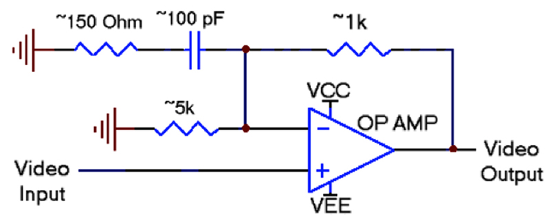
Figure 1: Single Stage Equalizer for 300 meters of Cat 5 cable
Transmission cables have improved, but the challenge is always the same: get more messages down longer cables faster. It may sound simple, but the longer the cable, the greater the losses. These losses would affect any type of transmission, but they are complicated at higher data rates, like video. The circuit block that compensates for losses in a system (like cable losses) is called an equalizer. Why is it called an equalizer? Maybe it is this simple: you want the signal coming out of the cable to be exactly the same as the signal going in. Since there are losses associated with cables, the equalizer is included to reverse those losses and make the output signal "equal" to the input signal. For example, Ethernet in all its forms is only specified to go 300 meters, HDMI on an entertainment center is usually limited to a few meters unless a special cable is purchased and USB peripherals need to be within 5 meters of the desk top. In addition, if you are installing security cameras, they need to be within 300 meters of the console or the picture will suffer. Buildings are getting bigger all the time. Think of all of the video displays in an airport. Consider the opportunity to run video ads in a supermarket or shopping mall while having the ability to control all the ads from a central hub. What about video feeds from the security systems at these places or at business complexes? Solutions to Long Cable Degradation One can use a higher voltage at the input. This higher voltage, just like pre-emphasis, boosts the signal at the source end and hopes that more gets to the far end, but this can be hazardous. Imagine that we wanted to send a video signal down a mile of Cat 5 cable (24AWG twisted pair), and let's say that the attenuation measured at the critical 3.58MHz color subcarrier frequency is 70dB. To get a volt of signal at the output of the cable, we would need to apply over 3000 volts at the source! Even if we managed the heroic electronics necessary to make a 3000-volt video signal, we would end up driving 30 amps into a skinny 24AWG twisted pair. It would explode in a shower of sparks and molten copper. This leads us to our second solution, equalization. An equalizer is a circuit that restores a signal that has been degraded by a length of cable. In our example, the signal needs a 70dB boost at high frequencies (the complete video signal takes a bandwidth of 5MHz or so) to make a nice picture. That's still a factor of 3000, but now it is a gain factor instead of a voltage. Let me restate, instead of forcing the source end of the cable to a very high voltage, we allow the signal to drop by 70dB, and then boost it at the output using amplification. In this way, there is no stress to the cable and no exploding wires. A single stage equalizer can easily boost about 14dB. If we put 5 of them in a row, we have our required 70dB of boost. Is that all there is to it? What could possibly go wrong? In a word: noise. All electronic amplifiers have noise, and if it is too high, it will swamp our video signal. Remember, the noise at the input of a circuit receives the same gain as the signal. (Those of you that remember rabbit-ear TV antennas know what I mean.) In particular, to get acceptable video at the far end, our equalizer noise must be at least 30dB (about 32 times) smaller than the video at the input to the equalizer (fussy people want 40dB or more—which is 100 times smaller). Remember that the signal at the output is already 70dB below the source level, due to cable attenuation. That's 100dB of dynamic range, or about 100,000:1. So we can avoid exploding wires only by building incredibly low noise equalizers. Fortunately, modern silicon processes are capable of this feat. Equalizer Circuits To dig a little deeper into the circuit specifics, let's start with the simple schematic of a discrete equalizer stage and build from there. The simple circuit in Figure 1 is designed to equalize 300 meters of Cat 5 cable. It is a high boost circuit, and many discrete video equalizers have been built this way. The amplifier is a low-noise op amp with sufficient gain-bandwidth to create the required 14dB of boost.
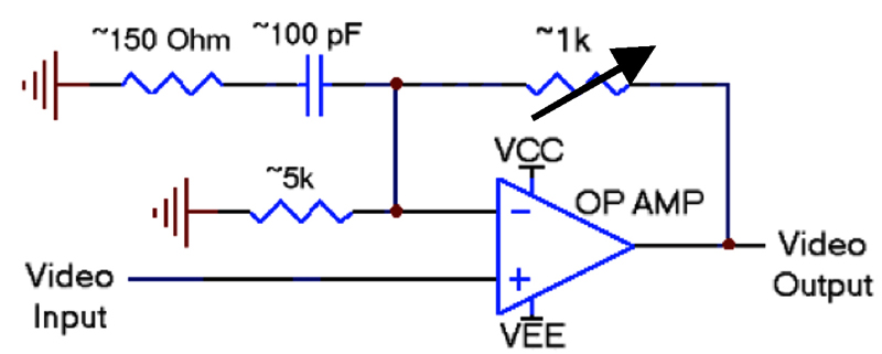
What happens if the cable is shorter than 300 meters? For shorter transmissions, we would need to reduce the amount of boost to match the cable length. Figure 2 shows a simple approach—make the feedback resistor a potentiometer.
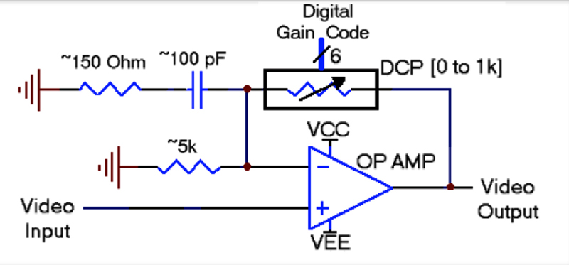
But we may wish to control the equalization from a microcontroller or digital logic, so it would be nice if there was a digital input for that variable resistance. We can solve that problem using a digitally-controlled potentiometer (DCP), as in Figure 3.
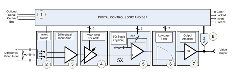
Building the Whole System The ability to build this circuit on one piece of silicon gives great advantages in cost, functionality and programmability. Figure 4 shows a simplified diagram of a complete automatic equalizer. There are eight blocks, so let's take it a stage at a time and investigate the function of each. The loop control and user interface are implemented with a modest number of gates of digital control logic (Block 1). The logic determines how much the signal needs to be equalized and how to adjust the equalization. Since no two chips are exactly the same, trim codes for the equalizers and filters ensure that each chip behaves the same. Block 2 is a simple addition that makes installation easy. Since the video cable in this case is twisted pair, it is possible to swap the wires, effectively inverting the signal. This circuit notices if the wires have been switched and inverts the signal to compensate. Also, since the video cable is a twisted pair (2-wires), our input stage must be differential. Block 3 shows the differential input amp that receives the signal from the twisted pair wire. At this point the signal has differential video (the intended signal) and common mode noise (corrupting signal from power lines and other nearby equipment). The differential input amp removes the common mode noise, leaving only the video signal. This video signal is expected to be a 1V peak-to-peak signal. Of course, cameras and other sources may vary. The automatic gain control (AGC) amplifier, Block 4, adjusts for variations in the overall video level. The core of the equalizer is responsible for boosting the high frequencies that were lost in transmission over the long cable. These stages need to be very low noise (they should not generate much of their own noise) and they need to reject any power supply noise (they should block noise from outside sources). Block 5 is simply five of the equalizer stages we discussed in the previous section. Block 6 is a noise filter. When the equalizer is configured to boost 5MHz, it may continue boosting all the way to about 10MHz before beginning to roll off. This extra boost does not enhance the signal, it just amplifies noise! Therefore, we need to include a sharp cutoff low pass filter to reduce the effect of noise above 5MHz. Once the signal travels through the noise filter, there is one more op amp stage (Block 7) before reaching the output. This output amplifier provides sufficient gain and drive current to interface with other video equipment. Finally, Block 8 is an analog-to-digital converter. This circuit samples the output and feeds it back into the digital control circuitry. If anything goes wrong, the control circuitry can adjust the other blocks in the equalizer to fix it. For example, if the output starts to droop, the gain amplifier (AGC) could be turned up to compensate.
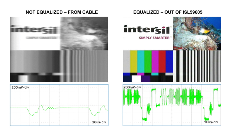
Visual Results Figure 5 shows a high quality source image after 1 mile of Cat 5 cable, with and without equalization. Remember that an unaided video signal can travel down around 300 meters of cable. As the length of the cable increases, the color information is lost. As the cable gets even longer, the images smear and text becomes unreadable. With the complete single-chip equalization solution (ISL59605), just described, all the picture details have been restored even after the signal has traveled over 5,000 feet (>1500m). Conclusion The ISL59605 (MegaQ) represents the application of advanced analog and digital techniques to the problem of long cable equalization. It provides automatic sensing of video signal parameters and implements appropriate correction and equalization. It requires no user intervention in most applications and provides full bandwidth video output from a variety of cable types and lengths. www.intersil.com


