Author:
Ralf Hickl, Product Sales Manager Automotive Business Unit (ABU) at Rutronik
Date
12/21/2022
 PDF
PDF
Click image to enlarge
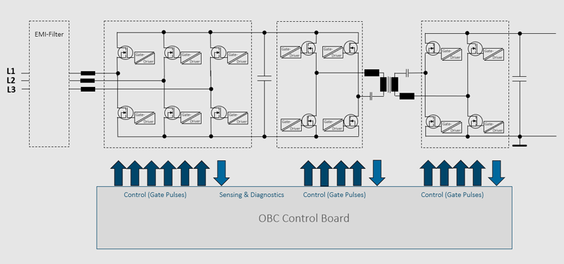
Figure 1: Simplified block diagram of a bidirectional charger
For BEVs (battery-electric vehicles), low power (kWh/km) is essential. Its calculation often not only includes the power from the battery but also the power required by the AC Wallbox to charge the battery. Charging losses in the onboard charger (OBC) therefore affect this figure directly. To ensure a low power BEV, it is essential to have the most efficient charger possible onboard.
The block diagram in figure 1 shows a bidirectional, 3-phase onboard charger. Beside battery charging, bidirectional chargers also allow the reverse flow of power from the vehicle battery to the grid. BEVs can thus help buffer the grid at peak load times. Yet another option is to use the vehicle as a power generator in isolated operation, a method Sono Motors is pursuing for its Sion, for example.
In this case, an OBC with four main blocks is recommended.
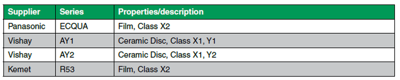
Block 1: Filter and PFC
Block 1 contains the filter for suppressing conducted electromagnetic interference (EMI filter). With regard to grid impacts, the OBC must comply with standard IEC 61851-21-1 (Electric vehicle onboard charger EMC requirements for conductive connection to AC/DC supply).
Together with the transistors of the grid inverter, the inductors are also part of the power factor correction (PFC).
Click image to enlarge
Table 1: Series proposals for interference suppression capacitors (Y, X) qualified to DIN IEC 60384-14 and AEC-Q200
Block 2: Grid inverter
Block 2 consists of the grid inverter. Depending on the direction of power flow, it works as a rectifier or inverter. Through pulse width modulation (PWM) of the input transistors, it simultaneously ensures high power factor correction (PFC) in interaction with the inductors in the phase lines.
Basically, the trend is toward higher switching frequencies (carrier frequency of PWM). The higher the switching frequency,
· the smaller the passive components can be,
· the quieter the vehicle (anyone who has walked passed a StreetScooter in idle mode or an active first generation high-power charger knows what is meant),
· the greater the power density of the overall system,
· and, unfortunately, the greater the switching losses.
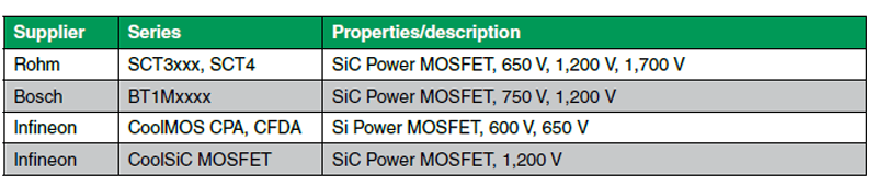
High switching frequencies are enabled by wide-bandgap semiconductors, i.e. diodes and MOSFETs made of silicon carbide (SiC) or gallium nitride (GaN). Automotive-qualified SiC-based MOSFETs are offered by Rohm and Infineon, for example (Table 2).
They are available with ever smaller RDSon and lower gate-drain capacitance to gate-source capacitance ratio. Small RDSon counteract conductivity losses, while small parasitic capacitances in the MOSFET benefit switching losses and switching behavior. The possible elimination of negative gate voltages simplifies the circuitry design for the gate driver and is easy on the budget.
Rohm supports its latest generation of SiC MOSFETs with a half-bridge evaluation board (e.g. P04SCT4018KE-EVK-001), which can be flexibly configured for various gate voltages.
SiC MOSFETs require suitable gate drivers with galvanic isolation between switching and control potential. They provide the necessary gate voltages and currents to switch the MOSFET on or off reliably. Some models also feature additional functions, e.g. monitoring for overcurrent or desaturation (DESAT) with feedback of the diagnosis to the control electronics (Table 3).
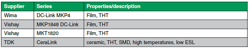
The grid inverter feeds the DC link on the grid side. There is also a DC link on the battery side, namely that of the traction inverter. The voltages in both DC links are smoothed and buffered with capacitors. The alternating currents (ripple currents) caused by the grid inverter and the DC/DC converter flow through these DC link capacitors. Important selection criteria for low power loss and heat generation are, therefore, low ESR (equivalent series resistance) in the switching frequency range and low ESL (equivalent series inductance). Film capacitors meet these property requirements. Alternatively, new ceramic capacitors with a special dielectric from TDK Epcos are available (CeraLink). Unlike conventional ceramic capacitors, their capacitance is not reduced by a high charge with DC voltage (DC bias) but increases up to the nominal voltage level (Table 4).
Click image to enlarge
Table 2: Power MOSFETs

Click image to enlarge
Table 3: Gate Drivers
Click image to enlarge
Table 4: Capacitors
Block 3: DC/DC converter
Block 3 is the DC/DC converter in CLLC topology. It consists of a half-bridge, an AC-coupled pulse transformer, and a synchronous rectifier (half-bridge) on the battery side.
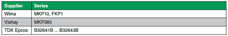
The DC/DC converter adjusts the voltage levels of the grid-side DC link and battery, transferring power from the primary to the secondary side (charging) or vice versa (generator / isolated operation or grid feed-in). The pulse transformer also galvanically isolates the electrical system from the public grid. Together with the capacitors of the series resonant circuits, the pulse transformer has a significant impact on the efficiency and power loss of the converter since the entire transmitted power flows through both components. An important selection criterion for resonant capacitors is, therefore, their loss factor tan δ. The smaller the loss factor, the lower the capacitor power loss and the better the efficiency. Together with the capacitance required for the resonant frequency, these conditions usually lead to the choice of film capacitors (Table 5).
Like the resonant capacitor, the pulse transformer is also a high-performance component. To achieve high efficiency, it must also generate as little heat as possible, i.e. offer low power loss. The power loss is composed of core and copper losses. While eddy current losses and remagnetization losses contribute to core losses, copper losses are determined by the ohmic resistance of the winding according to P = I²R. Due to the skin effect, the resistance depends on the frequency and increases with rising frequency.
The core material of the pulse transformer should be characterized by high saturation field strength and low remanence with high permeability. The higher the permeability of the core material, the fewer windings a coil requires achieving a given inductance. Shorter coil wires, which have a lower resistance, are sufficient for a coil with less windings. A high saturation field strength allows the core material to be designed in a highly controlled manner. Thus, a large portion of power can be transferred per period. High electrical resistance of the core counteracts eddy current losses. Its design ideally ensures defined leakage inductances on the primary and secondary side. Together with the resonant capacitor, the leakage inductance forms the resonant circuit. Alternatively, a low-leakage core can also be used. However, in this case, separate resonant inductances are required.
The densest possible winding, a rectangular conductor cross section, or a band result in a short conductor length and a high degree of filling of the coil former.
A pulse transformer with a compact design is advantageous for automatic printed circuit board assembly. Rutronik helps its customers find the pulse transformer that ideally matches the individual design. Sometimes a bespoke design is necessary. The suppliers TDK, Vishay, and Pulse are at hand, as development partners for such pulse transformers.
Click image to enlarge
Table 5: Film capacitors
Block 4: Control electronics
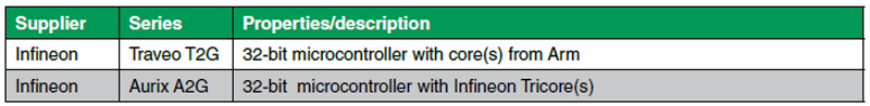
Block 4 shows the control electronics. Based on measured values, a microcontroller generates the control signals for the power semiconductors in the inverter, the DC/DC converter, and the synchronous rectifier. Depending on the functional safety requirements, derivatives from Infineon’s Traveo T2G series (up to ASIL B) or from the Aurix A2G series (up to ASIL D) are suitable (Table 6).
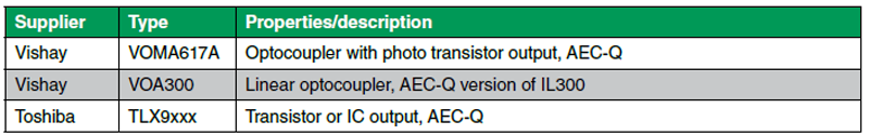
On their way from the high-voltage side to the control side with non-hazardous low voltage, the signals must be galvanically isolated. Components for the galvanic isolation of signals are, e.g., optocouplers from Vishay or Toshiba. Vishay’s VOA300 is an optocoupler for the transmission of analog signals and the automotive variant of the well-known IL300. It includes a transmit LED and a pair of matched receive LEDs. If one of the receive LEDs is included in a negative feedback circuit on the control side, good linearity of the current transfer characteristic between the transmit LED and the second receive LED is achieved (Table 7).
Click image to enlarge
Table 6: Microcontrollers
Click image to enlarge
Table 7: Optocouplers
HV connectors
The HV connectors from Amphenol (Table 8) must be mentioned in this respect. They ensure compatibility with Webasto’s Vehicle Interface Box, which is used by numerous OEMs and conversion specialists.

Click image to enlarge
Table 8: HV Connectors
Evaluation boards
As with the design of a bidirectional HV switch for 800 V/50 A ), Rutronik Automotive is collaborating with its partners on a reference design for an OBC. The design of the HV switch combines the functions of a conventional fuse with those of a switch. Cutting-edge 1,200 V SiC MOSFETs provide low conductivity losses and low power loss, thus making passive cooling sufficient. Until Rutronik’s new reference design for the OBC has been completed, Infineon’s REF-DAB11KIZSICSYS illustrates the implementation of a bidirectional 11 kW DC/DC converter in CLLC topology with 1,200 V and 1,700 V CoolSiC MOSFETs.
Summary
The long-term development of the OBC is quite exciting: Does it migrate into the charging cable as a kind of plug-in power supply thanks to modern components with high power density? Will it be just an equipment option in the future due to the development and spread of the charging infrastructure? Since during the journey it is just useless ballast. It competes with DC charging stations that bypass it and with battery swap technology. Nevertheless, as long as it is needed, it should be as efficient as possible.