What to Consider in Regard to Switching Frequency
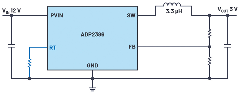
Figure 1. An ADP2386 buck converter with its switching frequency set with resistor RT.
Switch-mode power supplies switch with a frequency that is either fixed, adjustable, or synchronized to an external clock. The value of the switching frequency determines the physical size and, accordingly, the cost of a supply’s capacitors and inductors. There is a trend toward higher switching frequencies to allow for the design of compact and low-cost circuits.
The built-in oscillators in switching regulator ICs are usually specified for very wide frequency ranges in their data sheets. For example, the monolithic ADP2386 buck converter IC has a guarantee of ±10% of the set switching frequency. Other common switching regulator ICs are specified for ±20% or even more. An ADP2386 set with an RT to a switching frequency of 600 kHz can switch at 540 kHz and at 660 kHz in extreme cases, given the ±10% component variation in switching frequency of the ADP2386.
This possible switching frequency variation of 20% in total must be taken into account when designing a circuit because the peak currents across the inductor differ depending on the actual switching frequency. As a consequence, the inductor current ripple has a direct effect on the output voltage ripple.
Click image to enlarge
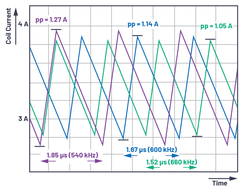
Figure 2. Coil current ripple peak to peak influenced by switching frequency variation.
Figure2 shows the effect of the switching frequency on the inductor current ripple. The nominal switching frequency of 600kHz is shown in blue. The minimum (540kHz) switching frequency is shown in purple and the maximum (660kHz) in green. At a nominal setting of 600kHz, we see a peak-to-peak current ripple of 1.27A when the regulator switches at 540kHz. However, with the same frequency setting of 600kHz, a switching regulator can also switch at 660 kHz, which corresponds to a current ripple of 1.05 A. In this example, a coil current ripple difference of 220 mA can result due to the variation in switching frequency from component to component in a circuit. This is over the entire permissible temperature range.
The setting of the current limit of a switching regulator must be coordinated with this effect. The peak currents must be low enough to ensure that any existing overcurrent protection is not activated during normal operation.
Note, all other variations that could also occur, such as variations in inductor and capacitor values, were not taken into account in this example.
For the output voltage ripple, the corresponding change in current ripple yields the values shown in Figure 3. The circuit is designed such that a voltage ripple of 4.41 mV occurs at a switching frequency of 600 kHz. For a switching frequency of 540 kHz, the voltage ripple is 5.45 mV; at 660 kHz, a voltage ripple of 3.66 mV can be seen.

Click image to enlarge
Figure 3. Changes in output voltage ripple due to switching frequency variation in a switch mode regulator IC.
For the purposes of this example, the only component variation considered is that of switching frequency over the permissible temperature range. In practice, there are many other variables, such as variations in the real values of the inductor and the capacitors. These are also affected by the operating temperature. However, it can also be assumed that, in most cases, the actual variationin switching frequency will not reach the limiting values of ±10%. Normally, the behavior will appear around the typical value in the middle of the specified range. For a systematic consideration of all dynamic variables in a power supply, a Monte Carlo analysis provides answers. Here, the variations of different components and variable parameters are weighted according to their probabilities of occurrence and linked to one another. Monte Carlo analyses can be performed with the freely available LT spice simulation software from Analog Devices.