Realizing LEDs' performance potential requires drivers that simultaneously meet multiple criteria.
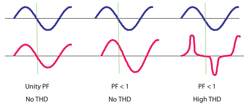
Figure 1: Incandescent light bulbs (blue curves) are purely resistive, LEDs (red curves) are not.
LEDs are gaining significant traction in the lighting market due to their long operating lifetime, low running cost, and ease of control for specific applications. However, in order to realize all of these benefits, you need to specify correctly your LED drive to obtain the required performance. With a potential lifetime of 100 khrs or more (if you operate them correctly), no filaments or tubes, no mercury, easy to control light wavelength, and significantly greater efficiency, it's easy to see why this is the right choice of lighting source going forward. LED chip manufacturers have been playing their part by improving their products over the last number of years; the companies developing drivers must play their part as well. What specifications your driver should meet The driver's primary requirement is to convert AC power to DC power. In doing so, it must also deal with PFC (power-factor correction) and THD (total harmonic distortion) issues because an LED load is not purely resistive (Figure 1). The driver must also meet safety and EMI requirements as well as circuit protection requirements such as OCP (over-current protection), SCP (short-circuit protection), and OTP (over-temperature protection). Additionally, the electrical design alone does not completely determine the driver's performance so one needs to pay attention to the interaction between mechanical-design decisions and electrical performance. For example, polyurethane-based potting compound is more cost effective than a silicon-based material but, with its dielectric profile, will offer challenges in terms of EMI performance.
A real-world example The LDB series product definition required the Excelsys design team to meet a number of market-leading requirements in a cost-effective manner.
- Efficiency: ? = 91% at 100 W
- Conducted & radiated emissions: Meet EN 55015
- Input Range: 90 to 264 VAC
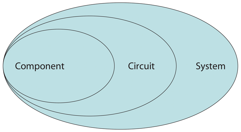
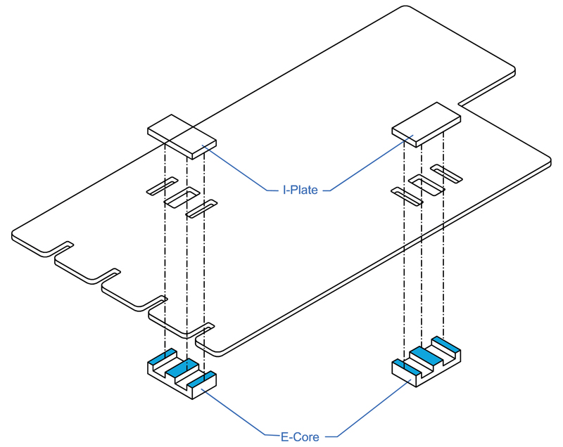
The future of power supplies We will continue to see more integration from vendors. Currently, designers select components for a circuit. Circuits assemble into systems. Eventually, engineers will design systems as integrated components, leading to an overall decrease in size (Figure 3).
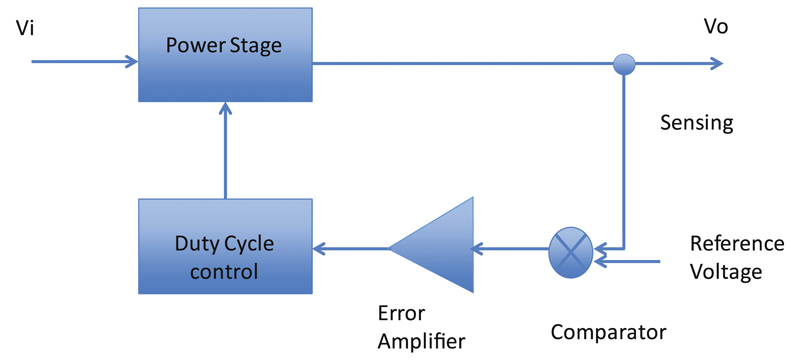
However, a more significant improvement will be the closing of the control loop with a digital controller. This will allow both improved performance and further interaction with the supply. A digital control loop has many advantages over its analog counterpart in that we can now dynamically optimize the control loop for all operating conditions by moving poles and zeros on the fly (Figure 4). Digital control also provides us with a means to communicate with our power supplies in order to understand if, for example, they are operating within specified limits. Digital control, and the communication it affords, also can provide get cycle-by-cycle feedback on the supply's performance. Of course, you can achieve this by adding a microcontroller for digital power management, but with a digital loop, you can implement this option more cost effectively. With a digital power-control loop, you can also integrate some additional features without increasing your analogue component count.
Ongoing research into magnetics is proving very successful, and will result in significant improvements in overall power density. Incorporating the primary and secondary windings into the PCB and inserting the core through pre-cut holes in the PCB reduces the height and size of the transformer design and results in a much lighter component (Figure 5). The LED driver of the future will be significantly different from the one we see available on the market now. Greater efficiencies will become the norm, as will greater degrees of integration to support increasing system complexity in terms of power monitoring and performance. More integration of SOCs (Systems on Chips) will continue to reduce the size, whilst maintaining reliability of the overall design. While no single element will cause a rollercoaster effect, incremental and continuous improvements will influence driver designs. www.excelsys.com


