When to Use Single vs. Dual DC/DC Buck Regulators
Many applications require multiple power rails. Some designers use dual output regulators to reduce the number of integrated circuits (ICs)
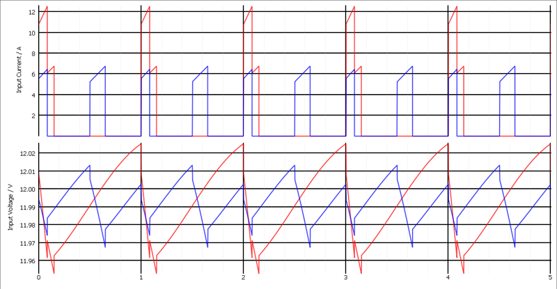
Figure 1: Input current and ripple with in phase switching (red) and out-of-phase switching (blue)
There are trade-offs to make when choosing between a single output regulator and a dual output regulator. In this article, I will discuss the advantages of both and highlight when to use one or the other, using the single 6-A TPS543620 output DC/DC regulator and dual 6-A TPS541620 output DC/DC regulator from Texas Instruments as examples.
When to use a dual output regulator
Dual output regulators have an advantage over single output regulators in several applications. You might consider a dual output regulator when your design requires the smallest solution size, such as in solid state drives. You might also opt for a dual output regulator when the point of load, such as a data converter or processing unit, has multiple colocated power rails, thus enabling you to place the regulator next to the device it is powering with minimal routing. Finally, a dual output regulator can offer increased flexibility by paralleling the two outputs together to power a rail requiring twice the current.
A dual output regulator can also help shrink solution size. Even if the package size of a dual output regulator is twice the size of a single output regulator, component clearance requirements require a larger area for two single output regulators. For example, if design rules require a 1-mm clearance around ICs, a 5-mm-by-3-mm dual output regulator will take up 24 mm2, while two 2.5-mm-by-3-mm single output regulators will take up 28 mm2. Those of you with designs requiring more clearance will see additional benefits from the dual output regulator.
Another way a dual-output regulator minimizes solution size is by reducing the required input capacitance. When the high-side MOSFET of a typical single-output buck converter turns on, there is a surge of current pulled from the input. With a dual-output regulator, the two outputs switch 180 degrees out of phase, so this surge of input current occurs at different times. This can also be accomplished with two single-output regulators that support synchronization to an external clock, like the TPS543620. However, synchronizing two TPS543620s to 180-degree out-of-phase clocks does require another external circuit to generate the out-of-phase clocks.
The results from the simple simulation in Figure 1 demonstrate the improvement from switching in phase for a 1-V and 1.8-V output, both with 6-A loads. The simulation parameters included a 1-MHz switching frequency, 12-V input, 1-µH inductor and 10-µF input capacitor, with 3-mΩ equivalent series resistance at each input. With in-phase switching (shown in red), the peak input current through the high-side MOSFETs is just above 12 A, the root-mean-square (RMS) current is 3.8 A and the peak-to-peak ripple on the input is 73 mV. With out-of-phase switching (shown in blue), the peak input current lowers to just above 6 A, the RMS current is 2.9 A, and the peak-to-peak ripple on the input is 46 mV. In this example, out-of-phase switching reduces the input ripple on the input rail by 1.6 times. You can take advantage of the out-of-phase switching by using 1.6 times less input capacitance, while targeting the same amount of ripple.
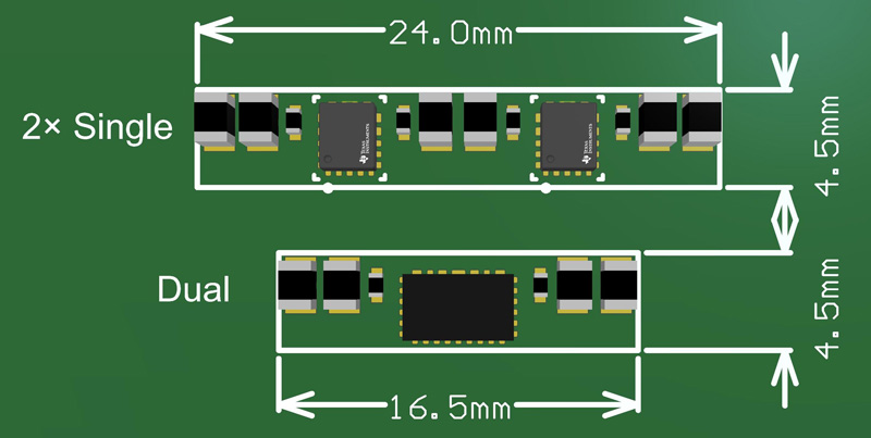
As an estimate of the potential space savings, two 0805 10-µF capacitors will help achieve an effective input capacitance near 10 µF on each input with a 12-V input. With two single-output regulators switching in phase, you would need three 0805 10-µF capacitors on each input for approximately the same input ripple. Assuming a required clearance of 0.5 mm between each capacitor, the area for the input capacitors for the dual output regulator is 17.5 mm2, while for two single output regulators it is 26.25 mm2.
Figure 2 shows a simplified layout of just the regulator and input capacitors for a size comparison between a dual regulator and two single regulators. The dual regulator results in an area savings of 30 mm2.
Click image to enlarge
Figure 2: Size comparison between single and dual regulators, including only the input capacitance
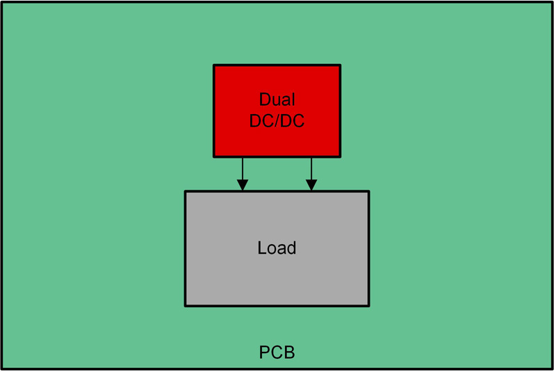
A dual output regulator is also advantageous when powering a single-load device that requires multiple power rails, as shown in Figure 3. You can place the dual output regulator next to the device it is powering with minimal routing.
Click image to enlarge
Figure 3: A dual regulator powering two rails on a single load
Finally, a dual output regulator can provide additional design flexibility by paralleling the two outputs together to power a rail requiring twice the current. If you are using a single output regulator, you will need an additional regulator to provide the higher current rails. Paralleling the two outputs of a dual output regulator to power a higher current rail helps minimize the number of unique components in the bill of materials. A dual output regulator with its outputs paralleled can have a lower steady-state output ripple compared to a single 12-A regulator. With its outputs paralleled, a dual output regulator can use two 6-A 1-µH inductors for half the output ripple of a single output regulator with a single 12-A 470-nH inductor, while achieving the same transient response performance.
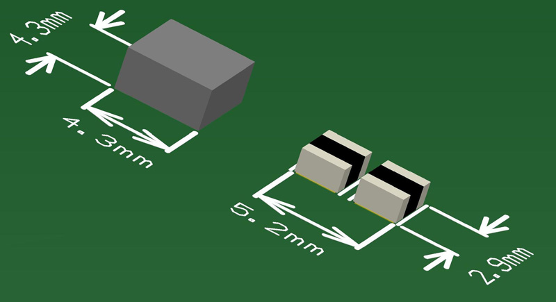
Alternatively, with a dual output regulator, two lower-current 470-nH chip inductors, with a size of 2.5 mm by 2.0 mm by 1.2 mm, will cost less and enable a solution with lower height. To have an approximately equivalent direct current resistance (DCR) with similar efficiency, a single higher-current 470-nH inductor would have to be 4.0 mm by 4.0 mm, with a height of either 2.1 mm or 3.1 mm. The high-current inductor has a DCR of 8 mΩ, while each low-current inductor has a DCR of 17 mΩ.
Figure 4 shows the difference in size between the single high-current inductor and two lower-current inductors. These dimensions are from the maximum specified dimensions of the inductors in their datasheet. The high-current inductor has a footprint of 18.5 mm2; the two low-current inductors have a footprint of 14 mm2, as well as a reduced height.
Click image to enlarge
Figure 4: Size comparison between two 6-A inductors and a single 12-A inductor
When to use a single output regulator
Single output regulators have an advantage over dual output regulators when the regulator must operate at high ambient temperature, such as in active antenna systems.
Two single output regulators are better than one for applications with high ambient temperatures because they can spread the power dissipation across two ICs, while a dual output regulator concentrates the power dissipation onto a single IC. On their respective evaluation module layouts, the single output regulator has an RθJA of 29°C/W, while the dual output regulator has an RθJA of 27°C/W. Assuming that the IC will heat up by only 40°C in the application, each single output regulator can handle an estimated power dissipation of 1.38 W for each output.
The dual output regulator, on the other hand, would be limited to 1.48 W – or only 0.74 W per output. This lower maximum power dissipation in the dual output regulator to keep the temperature rise below 40°C can limit the maximum current the regulator can support in a high-ambient-temperature application. The power dissipation in the dual output regulator could be reduced by operating at a lower switching frequency. However lower switching frequency increases solution size eliminating the main benefit of a dual output regulator – a lower solution size.
Additionally, given the trade-offs necessary in the pinout when putting two regulators in one IC, a dual output regulator can end up with a less-optimized pinout than a single output regulator. As a result, the dual output regulator may need to turn the power MOSFETs on and off more slowly in order to keep the voltage stress within the device ratings. The dual output regulator then has more switching losses than the single output regulator, contributing to larger differences in thermal performance. The single output regulator can have a more optimized pinout to enable the power MOSFETs to turn on and off more quickly.
The VIN and GND pins on both sides of the TPS543620 package enables you to put a bypass capacitor on each side of the power stage, minimizing printed circuit board (PCB) parasitic inductance. Minimizing the PCB parasitic inductance minimizes the switch-node ringing. The TPS543620 also has a large SW pin that allows a wider switch-node trace on the PCB layout to minimize PCB parasitic resistance.
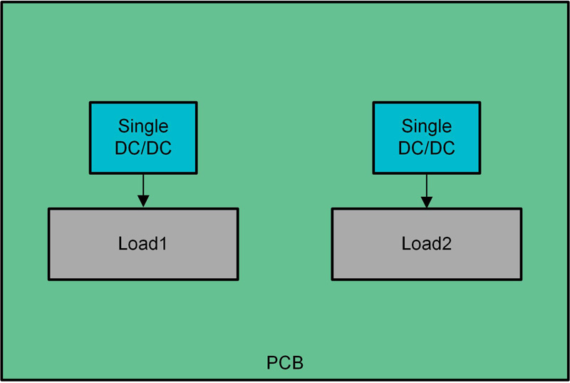
A single output regulator can also be easier to use when it comes to PCB layout by offering more options for layout optimization. First, single output regulators provide flexibility in where you can place each regulator, as shown in Figure 5. This is advantageous when the devices being powered are spread around the PCB. For a dual output regulator, you may need to make trade-offs in placement that result in long routing distances between the regulator and the device it is powering. Additionally, using two single regulators facilitates orienting the two outputs in more ways, which can make layouts easier to optimize when the board area is limited. With a dual output regulator, there is less flexibility in device placement.
Click image to enlarge
Figure 5: Two single output regulators, each powering two loads
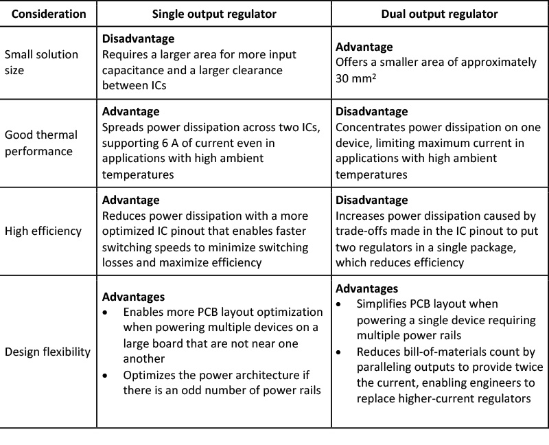
Table 1 summarizes the considerations to keep in mind when choosing between a single output and dual output regulators.
Click image to enlarge
Conclusion
There is no easy answer when it comes to choosing between single and dual output regulators. Both types of devices have their advantages, but the best choice depends on what is most important to your application. A dual output regulator solves the problem of limited board space by reducing solution size. The dual output regulator can also provide a simpler design by reducing the number of components in the bill-of-materials. A single output regulator can more easily solve the problems when operating in high ambient temperature because it will operate at lower junction temperatures enabling higher output current. The single output regulator can also simplify the design because it provides more flexibility.
Texas Instruments


