Use of thyristors in three phase motor control
The rising cost of utility bills, as well as government led programs to curb the impact of excessive electricity consumption, are driving consumers to replace household electrical goods with ones that offer greater levels of energy efficiency. The European Commission has set a target to reduce residential energy consumption by 27% by the year 2020. As a result products that are powered by three phase motors, rather than conventional single phase devices, are gaining in popularity. In traditional three phase motor designs, the relays used in magnetic starters have three mechanical contacts which control the supply of power to the motor terminals once the coil has been energised. However there are some shortcomings associated with this form of motor control, especially at higher current levels. Larger currents can cause sparking and arcing to take place across the contacts when the relays are activated/deactivated, damaging the contacts and thus having an adverse effect on the overall efficiency of the motor. This will cause noisier operation and shorten the product's operational lifespan. Design engineers are therefore keen to find an alternative to this approach, and are looking to solid state technology, instead of outdated electromechanical technology, for answers. Thyristors can deliver the switching functionality needed in a more efficient, less noisy and more reliable manner. They are also capable of switching at considerably faster speeds. A thyristor's construction means that it can withstand high voltage levels not allowing any current to flow unless the thyristor is triggered. Once it has been triggered it presents a low impedance path until the current is removed or it drops below a certain pre-defined level (referred to as the holding current). After the gate current has activated the thyristor it does not need to be maintained, meaning the device will latch in the low impedance state without gate current being continuously applied. When looking to create a three phase motor control system that incorporates thyristors, the engineer needs to give careful consideration to the various aspects that will influence the finished design. Otherwise the advantages of moving to a solid state approach will not be fully realised.
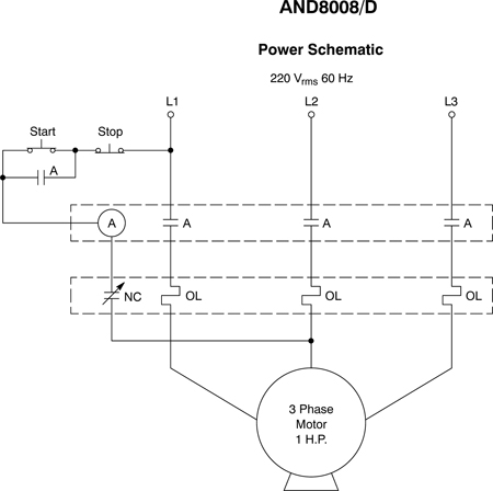
Three phase motors are made up of the stator windings and the rotor. The rotor induces the voltages of the stator frequency, and the currents produced correspond to the size of these voltages and the impedance of the rotor. Since they are induced by the rotating stator field, these rotor currents will produce a rotor field with the same number of poles as the rotor and rotating at exactly the same speed. An example of a traditional three phase motor controlled by a magnetic starter can be seen in Figure 1. The magnetic starter's coil (denoted by A) is energised and the mechanical switch contacts close so that a current flows through the motor. The motor is protected from voltage surges by an overload relay (NC).
By contrast Figure 2 describes a motor control system that is based purely on thyristors. Three thyristor devices (T1, T2, and T3) effectively replace the mechanical contacts utilised in magnetic starter design. A trio of optocouplers (O1, O2, and O3) supply the signal currents to these thyristor. In order to protect the thyristors from voltage transients, an RC �snubber' network (made up of a resistor and capacitor in series) is placed across each of the devices.

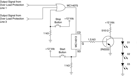
It is important to note that when looking to protect a circuit against voltage transients, snubbers must be used in the proper manner. Good snubber design relies on compromise. The voltage rate, peak voltage, and turn-on stress must all be taken in to account, and the most suitable balance found, or else unreliable circuit operation will result. The control signals for the two electronic overload circuits are received from the shunt resistors which are connected in parallel to the current transformers on two of the three main lines (L1, L3) for sensing the current flowing through the motor. The voltage in the shunt resistors will be dependent on the current in each main line. The voltage level will increase, causing activation of the overload circuits and thereby stopping the motor, should an overload condition arise in the motor's power circuit.
The ability to have variable speed control in the operation of white goods results in greater energy conservation. This can give manufacturers a competitive advantage as it means their products will have lower running costs, as well as allowing them to meet government environmental guidelines (such as EnergyStar® in the United States and the EU Code of Conduct here in Europe) before they become mandatory legislation. It is clear that thyristors can be used as a substitute for magnetic starters in three phase motor control - leading to more sophisticated and streamlined designs that offer longer operational lives and higher immunity to dv/dt. Employing these devices instead of electromechanical relays will bring about quieter operation and faster response, as well as permitting a higher degree of safety to be realised. As bulky permanent magnets will no longer be required, the systems created will also be less cumbersome. These attributes will help to accelerate the pace at which single phase motor appliances in homes are replaced by more efficient three phase options. www.onsemi.com