Why Brushed DC Motors Still Have a Role to Play in Modern Designs
It may have been overshadowed by more modern brushless designs, but the traditional brushed DC motor still has its place, particularly when costs need to contained.
A brushed DC motor will start turning when you apply a DC power source to its brushes. These make contact with the commutator (part of the moving rotor) and cause a current to flow through it. The fixed part of the motor – the stator – provides the constant magnetic field that interacts with the current flow through the rotor, thereby making it turn.
The contact point was typically made from graphite, which ensures it doesn’t fuse itself to the rotating surface in the event of a high-current short circuit, or a break/make action. And to ensure the contact pressure remains consistent, the contact point is generally spring-loaded.
The 20th century witnessed enormous industrial and technological leaps, and brushed DC motors played a big part. Consequently, prominent engineers, such as Charles Steinmetz, spent a lot of time analyzing motor technology. Their work looked at everything from manufacturing practicalities to detailed magnetic field and electromotive force equations. For many years, engineering students around the world were taught about DC motors.
But towards the end of the century, things started to change. Solid-state motor switches with insulated-gate bipolar transistors (IGBTs) and metal-oxide semiconductor field-effect transistors (MOSFETs) had matured and now enabled designers to create more efficient and reliable motors that were quieter, easier to control and more versatile. And with no brushes to cause radio frequency interference (RFI), electromagnetic interference (EMI), or simply wear out, brushless motors quickly became the preferred choice for many applications. They’re all around us today: from our household appliances to our cars, most of us use them on a daily basis.
But despite the popularity of brushless motors, there are still applications where a brushed design provides perfectly acceptable performance, reliability and cost-effectiveness. Low-priced toys are a great example, as are things like seat adjustors in cars.
What’s more, using brushed DC motors with modern controllers and IGBT or MOSFET switches, you can deliver surprisingly good performance – provided you understand the technology’s limitations.
Costs can be kept down, thanks to the minimal (or non-existent) need for control electronics. Moreover, you only need two wires to link the motor with the power source, thereby reducing both the need for space and the cost of connectors and cabling.
How Brushed Motors Work
Most motors work using the interaction between the electromagnetic fields on the fixed motor stator and the moving rotor/armature. Controlling these fields to induce magnetic attraction or repulsion results in movement of the rotor.
A simple brushed motor does not need any electronics. Connecting up a DC power source is enough to start the motor. While there’s a small contact angle dead zone that can cause start-up issues, some tweaks to the design can resolve this.
Swapping over the DC wires makes the rotor spin the other way, while speed can be controlled (to a certain extent) by changing the DC voltage. A brushed DC motor’s rotating speed is usually proportional to the electromagnetic force (EMF) in its field coil. This force is equal to the voltage applied minus any losses from resistance. The motor’s torque, meanwhile, is proportional to the current it’s drawing.
But how does a brushed motor create the required rotating field to make the armature go around, in the absence of a controller?
The answer is that the motor does this itself. Two brushes, opposite one another on the motor housing, send the current via two commutator plates to the armature coils. Each commutator plate is semi-circular, covering just under half the armature. As the motor spins, the path of the current automatically reverses every 180°.
The armature’s magnetic field interacts with that of the stator. The latter is produced using permanent magnets or fixed coils on the body of the motor. The rotor’s magnetic field reverses as the rotor turns, which keeps the motor turning. This is because the field the motor coils generate continually switches, so is repelled or attracted relative to the field the permanent magnets or external coils are producing.
For a long time, using permanent magnets was only feasible in very small motors, because the larger magnets weren’t sufficiently powerful or practical. But the use of rare-earth materials led to the creation of high-energy permanent magnets, which in turn made brushed DC motors with such magnets a genuine option, both for fractional-horsepower applications and those requiring up to around 2.0 horsepower.
Using permanent magnets saves on power, because none is needed for an external field coil. But the price you pay for this efficiency saving is less control over the way the motor behaves. Choosing between a design using permanent magnets or field coils means trading off factors such as the cost, weight, size and controllability of the motor.
Brushed Motors: Delving in Deeper
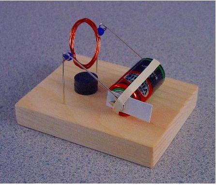
Basic brushed DC motors are wonderfully simple and elegant, so much so that they’re often used in children’s science kits to show the interactions between magnetism and electricity – and how this can be turned into useful motion. Figure 3 shows an example of a straightforward brushed DC motor, with no electronic control components and both the rotor movement and path of the current evident.
There have been plenty of variations on the basic brushed DC motor. Many of these are designed to overcome a particular weakness or improve performance for a specific use case. Most alterations are to the coils on the armature or the winding of the stator’s field coils. Others have added resistors and capacitors to control voltage and current, or change the relative voltage/current phase relationship. Let’s briefly look at some of these variations.
Many DC motors incorporate more than two armature poles. This provides a range of benefits, not least that it helps the motor start more reliably from any rotor angle (where the basic two-pole version has the two aforementioned dead zones). It also eliminates the possibility of current briefly flowing through a short circuit: while some systems can handle, this happening twice per revolution, a lot cannot.
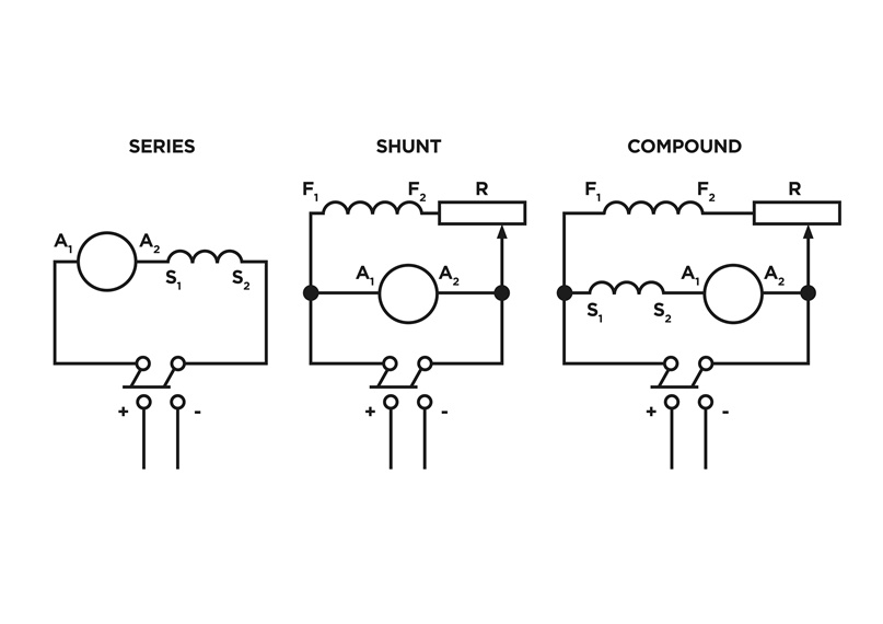
Stator field coil windings can be set up in different ways, with some common options shown in figure 4. The first is series-wound, where the field coils are connected with the armature coils in series, via the brushes. The second option is shunt-wound, where the field coils are linked up in parallel to the armature coils. The third variant, compound-wound, is a combination of the first two.
Click image to enlarge
Figure 2. In a series-wound setup (left), the field coils (S1 and S2) are in series with the armature coils (A1 and A2). In the shunt-wound configuration (middle), the field coils (F1 and F2) are wired in parallel with the armature coils. Taking a compound approach (right), field coils F1 and F2 are wired in parallel with the armature coils, while field coils S1 and S2 sit in series. Image source: http://www.industrial-electronics.com
Each design variation delivers a different blend of characteristics, trading off things such as control and performance, torque and speed, running and starting torque, and the ability to deal with load changes. More sophisticated designs even have independent controls for the rotor armature windings and stator field windings. This gives more precise control and increases flexibility.
The Continuing Development of Brushed Motors
Despite the popularity of brushless motors, work continues to manufacture and improve brushed designs. The basic motor design remains largely the same as it has always been, but with two key enhancements.
The first is the now common use of permanent magnets, in place of field coils. The second is the use of integrated circuits and electronic switching for both the feedback and coil-drive functions.
Take the Diligent 290-008, a 6V brushed DC motor, shown in figure 5. Its 1:53 reduction gearbox delivers enhanced torque of 0.7 kgf-cm (max). The six-lead connector carries two power leads and four for the built-in pair of Hall-effect sensors. The sensors provide motor feedback information on motor revolutions and the direction of the motor rotation.

Click image to enlarge
Figure 3. The Digilent 290-008 is a 6V brushed DC motor, 54mm long and with a 22mm diameter (plus connector). Two of the six leads are for power, while the other four are for a pair of Hall-effect sensors to detect rotation and its direction, as required for feedback control. Image source: Digilent
Without any load, this motor draws 220mA at a speed of 150 revolutions per minute (RPM). Its full-load rated current is 480mA at 125RPM, while the stall current is 1.8A with torque of 4.1 kgf-cm. This relatively small unit and its gearbox have a coil resistance of 3.3 ohm. Figure 6 shows the relationship between torque, current, speed, efficiency and output power (using a 6V supply).
A brushed motor can be connected directly to a DC rail, but it’s generally better to use a dedicated driver. This delivers the required drive current and protects the motor subsystem. An example of such a driver is Texas Instruments’ (TI) DRV8412 Dual Full-Bridge PWM Motor Driver, part of TI’s DRV8x range. The DRV8412 can drive two brushed or stepper motors independently, using high-efficiency drivers (up to 97%) that minimize thermal dissipation and are capable of delivering 2 x 7A continuous or 2 x 12A peak currents to the motors.
The driver’s small integrated circuit (measuring 6.1x14mm) protects the device against potentially damaging issues, including over-current, under-voltage and short circuits. It also incorporates two-stage thermal protection and a circuit that limits the current and prevents ‘false’ shutdowns when the load changes (e.g. when the motor starts). This capability works like a slow-blow fuse. Moreover, there’s an over-current detector that can be programmed to meet the specific requirements of a motor.
Products in the DRV8x range have separate ground and supply pins per half-bridge, meaning current can be measured using external shunt resistors, and that motors with different power-supply voltages can be used. This capability is invaluable in scenarios where you have motors of different sizes, such as you might on an external advertising display. This could include a big motor to rotate the display, and a smaller one to wave a flag to grab people’s attention.
Summary
For a variety of sound technical reasons, brushed DC motors have been overtaken by their electronically controlled brushless counterparts. However, there remain situations where brushed motors represent an attractive option, particularly where demands are lower and costs need to be kept down.
And by using a brushed motor with a motor driver, both the motor and the product it’s used in can benefit from numerous protections and operational benefits.
So, when you’re choosing a motor for your next product design, take some time to consider whether a modern brushed motor could actually be the best solution.