Why Higher Rack Density is Changing Interconnect Designs

Data center rack densities are increasing as generative AI fuels power demands, reshaping the power density, thermal management, and connection security requirements on the interconnects that support them
Figure 1: An example using the Saf-D-Grid Max connector demonstrates that, at constant ambient temperature, connector temperature increases as applied current increases
AI acceleration and high-performance computing (HPC) architectures are fueling an unprecedented rise in data center demand. Goldman Sachs expects global data center power demand to surge +160% by 2030, and AI server racks in 2027 will require 50x more power than cloud equivalents five years ago.
To meet this demand, data center rack densities are scaling at an aggressive pace. Traditional enterprise data centers operate near 8-10kW per rack, while larger hyperscale data centers are shifting toward 100 kW and beyond. Next-generation systems exceed 200 kW, late-decade roadmaps are predicting 600 kW per rack, and 1 MW is on the horizon for the largest applications.
As rack power densities increase, the performance, safety, and reliability requirements for the interconnects powering these racks are also being reshaped. Cables and connectors are small but critical design elements, carrying power throughout the data center’s infrastructure by connecting the points within the power distribution network. Engineers must evaluate how the current handling, thermal performance, compactness, and connection security requirements of interconnects are shifting as rack densities grow.
Why High-Power Performance in a Compact Footprint is Crucial
The most fundamental requirement for any power interconnect is the ability to safely carry the expected voltage and current. Specific connector power requirements vary widely for each individual data center. A few of the most recent data center power architecture trends include:
· High-Voltage DC Power: Hyperscale and AI-focused facilities with rack densities above ~150 kW are transitioning to high voltage DC distribution (±400 V / 800 V) to manage conversion losses and conductor size.
· Three-Phase AC: Many enterprise environments continue to rely on AC distribution while seeking additional ways to optimize power delivery. For example, some are pushing 480VAC three-phase power deeper into their power trains to take advantage of efficiency and operational benefits.
· Rack-Level Power Increases: Power distribution at the rack level has also increased. Power feeds for ICT equipment once operated near 5V, but current designs commonly use 24V or 48V distribution to support higher loads with improved efficiency.
As data center power designs evolve at a rapid pace, connectors must also evolve to meet the requirements of more specific and demanding power distribution models. Connectors that support higher voltages, higher amperages, and both AC and DC power deliver enhanced flexibility and can meet the demands of many different power architectures.
The physical footprint of a connector is another important consideration. The average cost to construct a data center surpassed $1,000 per square foot in 2025, and vacancy rates remain at record lows. To save space for ICT equipment within racks, connectors that meet increased power demands in the smallest footprint possible provide a clear design advantage.For example, standard IEC C19/C20 power couplers support 20A. The Saf-D-Grid® Max connector from Anderson Power is rated for up to 55A, providing 2.75x more power in the same panel footprint. Another advantage is that engineers can utilize Saf-D-Grid Max to support the same amount of power with fewer connectors.
ICT Connectors and Increasing Thermal Stressors
As data centers adopt power distribution models with more current, the amount of heat power connectors must withstand also increases. A connector’s temperature rise is a function of current load and contact resistance:

Therefore, as current increases, resistive heating scales accordingly. Figure 1 demonstrates that, at constant ambient temperature, connector temperature increases as current increases.
Selecting an appropriately-rated connector and wire size is important to avoid serious performance issues and safety concerns. This might include power contact damage, melting connector housings, or even fires.
How Connectors are Adapting to Thermal Management Strategies
Data centers utilize many different strategies to keep their systems cool, and connectors must be able to adapt. Traditional air-based cooling systems with hot/cold aisles for extra efficiency continue to be used by many enterprise data centers. To summarize a hot/cold aisle cycle:
1. Cooled air from the computer room air conditioner (CRAC) is delivered via perforated floors into the cold aisles.
2. The air passes through the server racks, cooling the equipment.
3. The heated air enters the hot aisles, rising to be collected by CRAC units in the ceiling.
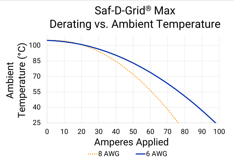
For connectors in these systems, the connector temperature rise plus the ambient temperature cannot exceed the maximum operating temperature of the connector. Current ratings are usually established when the contact temperature rise above ambient temperature reaches 30°C. The current must be derated (reduced) as ambient temperature increases or when smaller conductors (higher AWG) are used. Figure 2 shows the derating curve for the operating current of the connector over a range of ambient temperatures.
Click image to enlarge
Figure 2: An example with the Saf-D-Grid Max connector demonstrates that allowable current must be derated (reduced) as ambient temperature increases or when smaller conductors (higher AWG) are used
The temperature in hot aisles have traditionally hovered around the 40°C to 50°C range. However, as data centers strive to meet increased power demands, today’s hot aisle temperatures may surpass 70°C. Standard IEC C13/C14 appliance couplers are often limited to 70°C. Connectors like the Saf-D-Grid Series support up to 90-105°C to offer extra thermal headroom for hot-aisle environments.
Data Center Connectors and Liquid Cooling
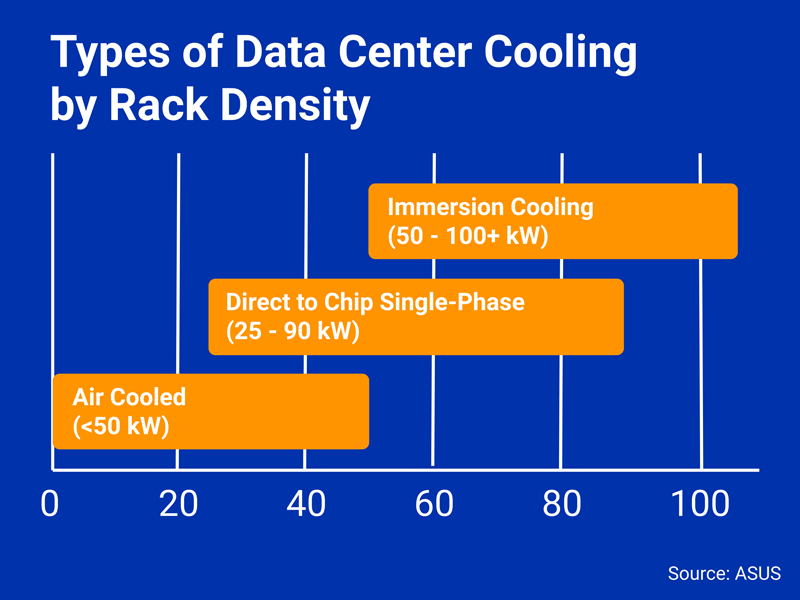
Large data centers are increasingly adopting alternative thermal management strategies, introducing new considerations for power interconnect designs. Generative AI and GPU-accelerated servers in HPC applications generate far more heat than traditional computational loads, straining the capabilities of convection cooling. Conduction cooling transfers heat more effectively, so data centers are submerging processors (direct-to-chip cooling) or entire servers (immersion cooling) into specialized dielectric fluids that absorb heat via convection. Liquid cooling is the Open Compute Project (OCP) industry standard for rack densities above ~50 kW (Figure 3).
Click image to enlarge
Figure 3: An approximate breakdown of cooling strategies by rack density. As rack densities rise, data centers must explore more innovative methods of cooling
Liquid-cooled systemsrequire connectors that can operate safely when submerged in dielectric fluids like fluorochemicals and hydrocarbons. The connector housing must resist degradation from the dielectric fluid used, ensuring the connector’s long-term integrity and reliability even when fully or partially immersed.
How Integrated Latches Enhance Connection Security
As connectors handle increased power demands, the security and safety of the connection while mated is important to evaluate. The results of an accidental disconnection under load could be catastrophic, potentially triggering an arc flash — or an electrical explosion with temperatures capable of exceeding 35,000°F (19,400°C).
To mitigate safety concerns for data center technicians, connectors with secure, integrated latches can be adopted. Latches are mechanical interlocks built into the exterior connector housing. By requiring manual depression, latches necessitate a person to intentionally unmate a connector and thus improve connection security.
Another important connector safety feature is touch-safe mating faces on both the plug and receptacle. This keeps technician hands isolated from the power contacts and minimizes the risk of contact with hazardous voltages. To ensure a connector is touch-safe, the connector should pass UL and IEC finger-probe (plug and receptacle) and 3mm probe tests (receptacle).
What Connectors Support Increased Power Demands?
Increasing power demands, safety requirements, and cooling systems are introducing new requirements for the connectors that power data center ICT equipment. Connectors that offer power-dense, secure, and reliable connectors will help meet the demands of tomorrow’s data centers.
One example is the Saf-D-Grid Series from Anderson Power. Saf-D-Grid supports both AC and DC power, features an integrated latch to prevent accidental disconnects, and is rated touch-safe in UL and IEC tests. The connector series is also prepared for cooling strategies with a maximum operating temperature of 105°C and a rugged housing that withstands exposure to many dielectric fluids.
The series includes three primary models:
· The original Saf-D-Gridis UL-rated for disconnect up to 30A, offering up to 7.2x the power of a standard C13/C14 connector within the same compact footprint.
· The Saf-D-Grid Three Phase 20 A is a C13/C14-sized connector rated for up to 20A, 480V line-to-line, and 277 VAC line-to-neutral. It is designed specifically to support unique three-phase AC power architectures.
· The larger Saf-D-Grid Max is designed for high-current applications in a C19/C20 footprint, delivering up to 55A of UL-rated current and up to 600V AC/DC of disconnect voltage.
The Future of Data Center Power Interconnects
As rack power densities increase, the current handling, thermal performance, and connection security requirements placed upon data center interconnects are also increasing. Connectors represent an important design element to evaluate as data centers scale to support next generation AI and HPC workloads.