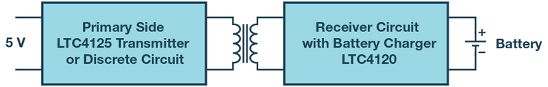
Figure 1: Inductive power transmission concept with primary side control and receiver
Wireless transmission of power has numerous advantages. For example, it makes fault-prone plug contacts redundant. Devices can be built into housings that are protected against moisture ingress. Users also don’t have to go to the trouble of plugging in cables. Most wireless power transmission applications lie in the field of charging batteries in portable devices.
There are a few established standards in this field. However, there are many applications for which no standard is necessary—hence, individually optimized power transmission can be used. Figure 1 shows one inductive power transfer concept. Two coils are brought close together and an alternating current is generated in the primary coil. Through the resulting magnetic field, an alternating current is induced in the secondary coil, like in a transformer.
In principle, the primary transmitter can be built with a simple oscillator and a few discrete components. This works well for transmission at low power levels. For higher power, an integrated transmitter circuit such as an LTC4125from Analog Devices should be used. The transmitter adjusts very precisely to the given resonant frequency. This enables maximum power transmission to be achieved with specific components. An LTC4125 can also detect foreign objects on the primary coil. For example, if a piece of metal is held against the coil, eddy currents are formed in the metal. They heat up the metal and, especially in the case of high power, can lead to injuries. At low power levels, a foreign object would only cause minimal heating and not present a significant risk. The LTC4125 can detect metal objects and then reduce the power or interrupt the powertransmission.
To save energy, an LTC4125 can adjust the transmitted power to the power requirements on the secondary side.
Click image to enlarge
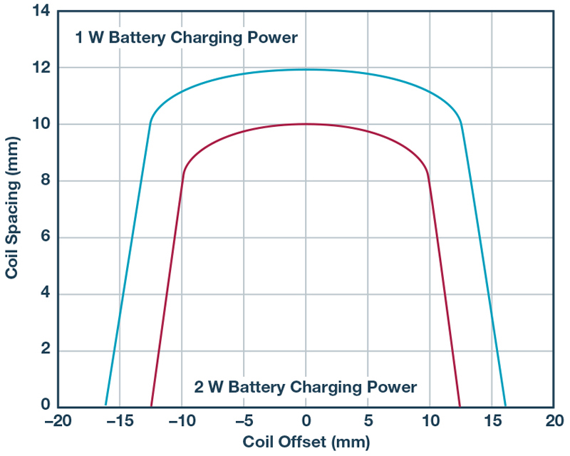
Figure 2: Effect of offset and spacing between the two coils
Figure 2 shows an example of a demonstration circuit with specific components. The graph shows what happens when the two coils are offset or separated by specific amounts. In a transformer, the coupling factor is usually between 0.95 and 1. In wireless power transmission systems, coupling factors of 0.8 to 0.05 are common. In Figure 2, the coil offset in millimeters is shown on the x-axis. The spacing between the two coils, also in millimeters, is shown on the y-axis. Thus, if the two coils are exactly vertically aligned (for example, the coil offset is zero) for a battery charging power of 1 W, the distance between the two coils can be up to 12 mm. The higher the power is, the closer and more precisely aligned the two coils must be. The transmittable power can be adjusted through the choice of circuit elements. However, the relationship between coil offset and coil spacing will be similar to that shown in the example.
For wireless power transmission over greater distances, RF power transmission can be used. There are test setups working in the ISM band. However, the transmittable power and the transmission efficiency are much lower than with the inductive coupling method described here.