Wolfspeed Enables Higher-Voltage Batteries for EV Systems
Scaling EV batteries from 400 V to 800 V
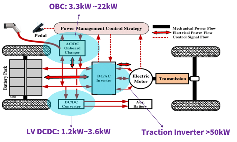
Figure 1: High-level view of an EV and several opportunities for Silicon Carbide technology
Silicon Carbide (SiC) technology has transformed power management in many markets, especially power delivery systems in electric vehicles (EVs). SiC provides advantages in terms of efficiency, power density, size/weight, thermal management, and reliability.
Advantages of Higher Battery Voltage
Many areas of an EV benefit from SiC technology (see Figure 1): the AC/DC on-board charger, DC/AC inverter (traction inverter), and the DC/DC converters. Currently, many commercial EVs utilize a 400 V battery architecture; as car-makers look to bring more value to the consumer, it is also possible to increase the battery voltage of the system. By moving to a higher voltage, most commonly 800 V, the system demands less current to deliver improved performance.[1] When designing a higher voltage / lower current designs, the overall systems can experience:
1. Reduced losses and improved efficiency.
2. Smaller components, which reduce overall weight and cost on wiring / sub-system components.
3. Decreased charging time, allowing drivers to have less anxiety over travelling longer ranges.
On-Board & Off-Board Chargers Supporting 800 V Batteries
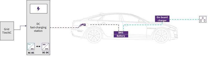
Let’s start with the on-board charger (OBC), which commonly range from 3.3 kW to 22 kW (depending on the size of the vehicle). OBCs can be bi-directional enabling vehicle-to-grid applications – an exciting opportunity for future distributed energy storage. Meanwhile, off-board chargers utilize varying power levels with and AC input converted to DC power for the on-board battery. Utilizing DC fast-charging configurations, batteries can be charged in as little as 30 minutes through creation of high power systems. Achieving this fast charging requires systems capable of operating with higher efficiency, improved power density, high ruggedness/reliability, and lower cost per kW delivered to be economical. Figure 2 shows a diagram of the entire EV charging infrastructure, including off-board and on-board building blocks connections.
Click image to enlarge
Figure 2: Electronic block diagram showing both the on-board and off-board EV charging infrastructure
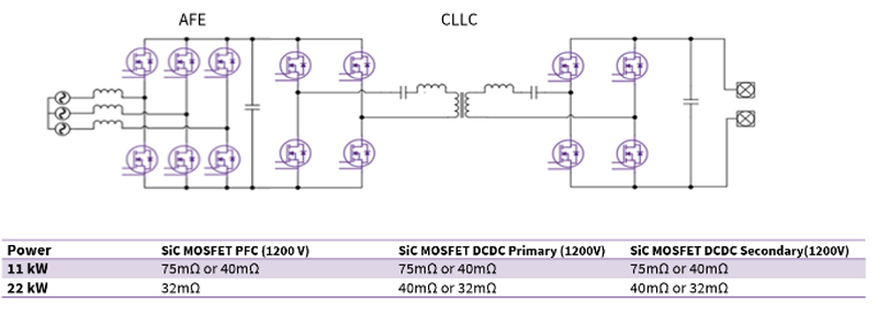
The shift from a 400 V to an 800V battery architecture requires an expansive portfolio of 1200 V SiC MOSFETs. To enable designers to understand best-practices to reap the benefits of these powerful device, Wolfspeed has also developed reference designs for OBCs. Figure 3 shows as the three-phase 22 kW bi-directional topology. This design utilizes MOSFETs with lower RDS (on) ratings (C3M0032120K/C3M0040120K) to achieve the higher power range (22 kW) and is capable of accommodating most battery-charging systems from 200 V-800 V. For lower power design, e.g, 11 kW, C3M0075120K/E3M0075120K can be used. While the industrial qualified devices (‘C’ part numbers) were utilized for this reference design, Wolfspeed offers equivalent automotive qualified portfolios (‘E’ part numbers) to support the different qualification requirements of the end consumer.
Click image to enlarge
Figure 3: Three-phase 22 kW bi-directional OBC reference design
Click image to enlarge
(3a) Schematic block diagram of 22 kW charger
Click image to enlarge
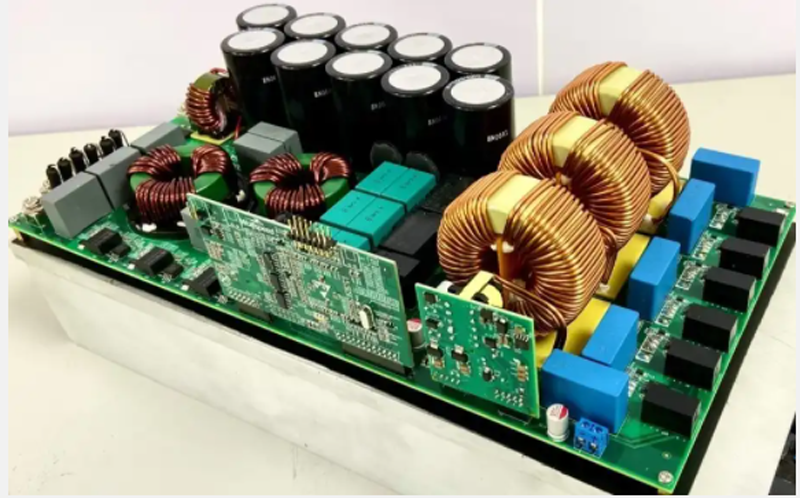
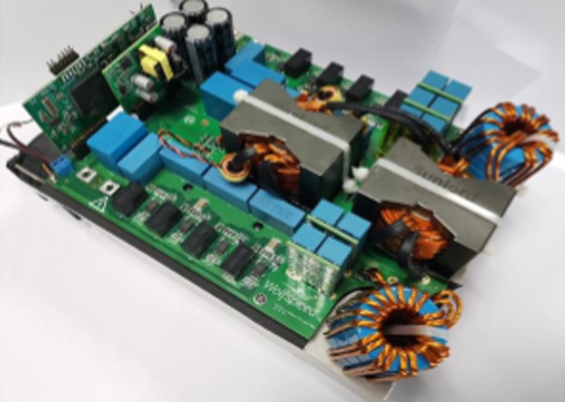
(3b) Prototype pictures – AFE (left) and CLLC DC/DC (right)
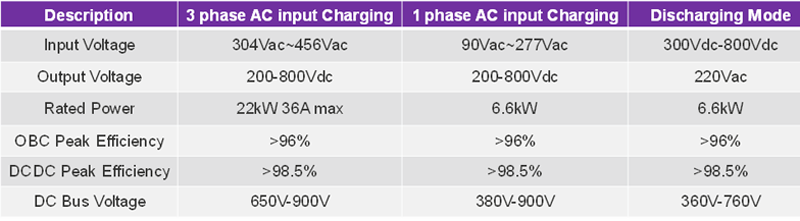
Figure 4 shows the charging specifications and modes associated with this 22 kW design.
Click image to enlarge
Figure 4: 22 kW OBC reference design charging specifications
Traditionally, a two-level, active front end (AFE) AC/DC converter is used for the OBC, but SiC allows for bi-directional operation, single and three-phase AC input compatibility, a lower parts count, and simpler control when compared to IGBT and T-type topologies. The C3M0032120K or E3M0032120K 1200 V 32ohm SiC MOSFET can be selected for AFE and CLLC converters, which help with electrical stress and thermal design.
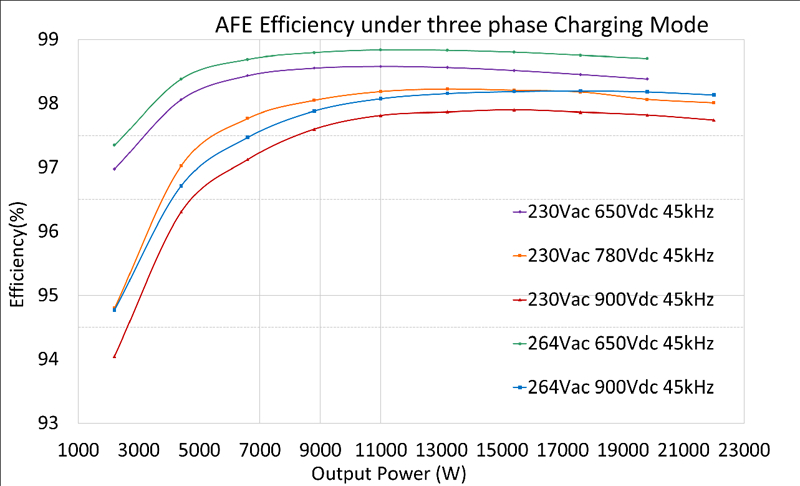
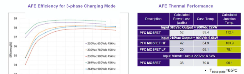
Figure 5 demonstrates the efficiency at three-phase AC charging, which includes 98.5% peak efficiency (around 38% lower losses than silicon) and a thermal performance that is well within the system/device limits.
Click image to enlarge
Click image to enlarge
Figure 5a & 5b: AFE efficiency and thermal performance for 22 kW reference design
Utilizing an off-board DC fast charger, a 30-minute charging time using a 400 V battery architecture can be reduced down to just 12-15 minutes – due to the higher power at higher battery voltage – without the need for increasing the size of the charging system. SiC’s ultra-fast switching and high efficiencies enable this system level improvement providing great benefit to EV consumers. An example of the high voltage benefits that SiC can bring to off-board chargers, Wolfspeed has developed the 30 kW 3 Phase interleaved LLC DC/DC converter reference design, CRD30DD12N-K utilizing their C3M0040120K 1200 V SiC MOSFET and C6D20065D/C6D10065A SiC Schottky Diodes. In this type of two-level system design, SiC offers:
● Up to 30% lower losses.
● 2-3 times faster switching speeds.
● 65% increase in power density.
● 30% fewer components.
● Potential for an overall lower system cost.
DC/DC Conversion Topologies used for Higher Battery-Voltage Range
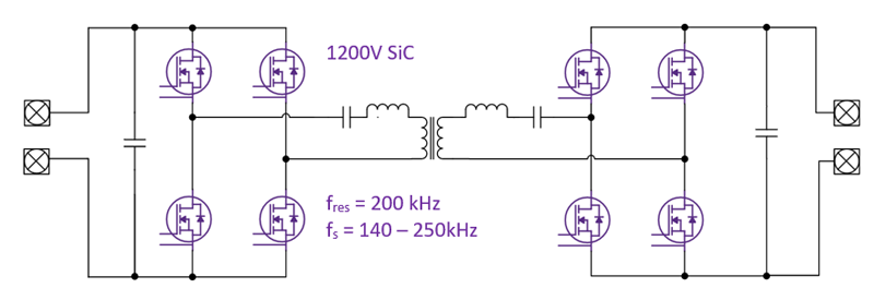
A 650 V Si or SiC solution, such as a cascade converter for an 800 V bus, typically operates in the 80-120 kHz range and has a higher parts count, higher conduction losses, higher control complexity with current sharing control and relay control (at the output), and an overall higher system cost compared to those designed at higher voltages. Figure 6 demonstrates a SiC-based, single, bidirectional two-level converter switching at 140-250 kHz and resulting in a lower parts count, higher efficiency, simpler control, and an overall lower system cost. In addition, it provides zero voltage turn-on, low current turn-off (lowering switching losses), and better EMI performance.
Click image to enlarge
Figure 6: A SiC-based, single, bidirectional, two-level DC/DC converter
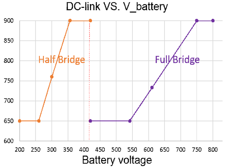
The design above supports a DC-link voltage of up to 900 V (battery voltage at 800 V), resulting in 22.6 Arms for DC-link side and 28.5 Arms for the battery side. A variable DC-link-voltage control section ensures that the CLLC runs close to resonant frequency, enabling higher system efficiency. Additionally, when battery voltage is low, the control switches to phase-shift mode. For lower battery voltages, the CLLC primary is run as a half bridge. See Figure 7 for the DC-link vs. battery voltage plot. The C3M0032120K / E3M0032120K can be used in this conversion too, as it provides the best figure of merit and is easy to drive (Vgs = +15 V).

Click image to enlarge
Figure 7: DC-link vs. battery voltage plot for a DC/DC converter
The 22 kW Bi-directional High Efficiency CLLC DC/DC converter reference design (CRD-22DD12N) described here offers many benefits, which are summarized below:
● High power density — 8 kW/L.
● Peak efficiency of > 98.5% in both charging and discharging modes.
● Bi-directional operation.
● Supports DC-link from both three-phase AC and single AC inputs.
● Supports 200 VDC - 800 VDC battery-voltage range.
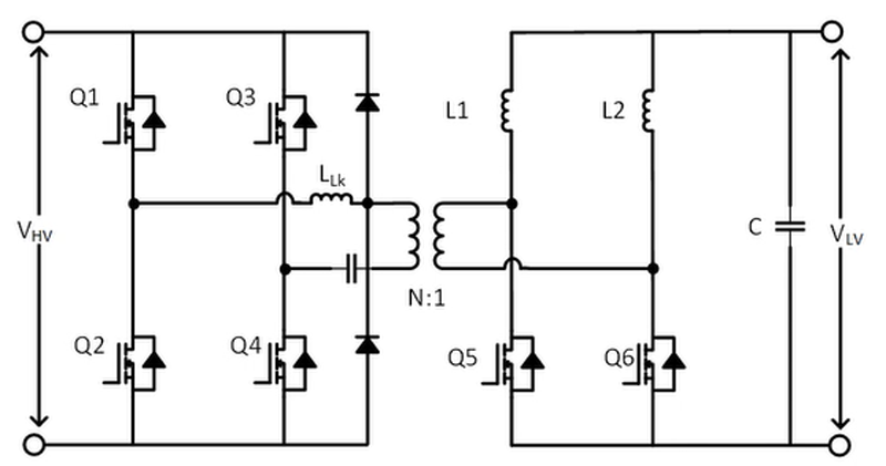
In EVs, a high-voltage-to-low-voltage converter (LV DCDC) is also needed as an auxiliary power supply to fulfill crucial functions like control, communications, and safety. This may consist of something like 800 VDC to 12 VDC; it is also becoming more common for these power supplies to require bi-directional operation for pre-charging purposes. Figure 8 shows a typical HV to LV Full Bridge Phase Shift (FBPS) DC/DC converter. The switches Q1 – Q4 can use Wolfspeed C3M0075120K/E3M0075120K for a 3.6 kW design with an 800 V DC input. The secondary side is a current doubler which can handle a high output current, since it’s split between the two inductors (L1 and L2) at the output. The output current ripple can also be reduced thanks to the current interleaving effect of the two output inductors.
Click image to enlarge
Figure 8: FBPS DC/DC Converter with a current doubler
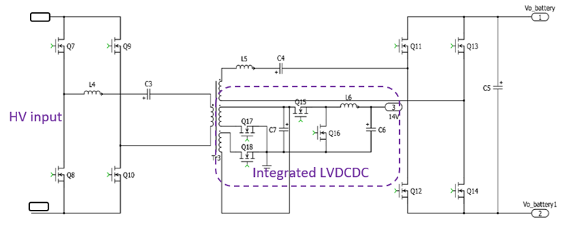
While the LVDCDC is currently separated from OBCs, the future may consist of fully integrated topologies that even further reduce size, weight, and cost, as shown in Figure 9. Two windings are tapped off from the main transformer to provide power for the low voltage output with secondary side control. In this way, the LVDCDC uses the same primary side power switches (e.g., E/C3M0032120K or E/C3M0040120K) and the same main power transformer.
![]()
Click image to enlarge
Figure 9: Integrated LVDCDC utilizing the same power transformer
Conclusion
In conclusion, higher-voltage battery packs used in EVs continue to increase in popularity as they improve efficiency, weight/cost, and charging times. As a result, power conversion topologies and their supporting components must devices capable of higher voltage operation. In addition to the power systems within the on-board and off-board EV charging infrastructure, SiC also has a major impact on energy-storage systems and power conversion across a number of other renewable energy and industrial markets. Similar topologies found herein can be applied to many different power system requiring an improvement in density and efficiency, see here for more on ESS systems and what advantages SiC can offer.
Wolfspeed offers an extensive portfolio of high-voltage Silicon Carbide MOSFETs and reference designs that can be used to instill confidence and provide a quicker time-to-market. To learn more about OBC applications and Wolfspeed’s products, visit:
https://www.wolfspeed.com/applications/power/automotive/on-board-charger/.
[1] 800-Volt EV Charging: The Other Palliative for Range Anxiety, IEEE Spectrum, April 04, 2022
(https://spectrum.ieee.org/ev-charging-800-volt#toggle-gdpr)