Accelerating Isolated Power Supply Design
Designing for harsh operating environments comes with unique challenges. Consider automated factories, where sensors and I/O modules are controlling industrial processes. Designing power circuits for these modules is tough because the modules continue to shrink in size, require ever lower power consumption and electrical isolation, and need to support a variety of applications. If you’re like many designers, you might be spending a lot of time and effort seeking the right voltage regulator controllers, transformers, inductors, and discrete transistors to support your application. In this post, I’ll discuss a methodology and tools that accelerate isolated power supply design.
Why is Isolation Important?
Isolation between a high-voltage input and a low-voltage output is essential for safety reasons. In offline applications where the powerline provides the input voltage, isolation protects the power-supply electronic load against accidental electrical overstress. Isolation also prevents the ground loops that can produce parasitic currents which disrupt the output voltage regulation.
A typical factory floor may use several modules, each of which can have up to 64 channels. With electric and magnetic interference and over-voltages, sensitive electronics inside a factory need to be protected. Each module has a programmable logic controller (PLC) that’s powered via an isolated step-down voltage regulator. In a digital input module (DIM), a rugged, voltage-level translator interface powers the sensor, takes in its information, and passes this data to the PLC via a digital isolator or optocoupler. The digital output module (DOM) features a similar power, signal, and isolation chain that leads to the on-board driver and interfaces to the external actuator.
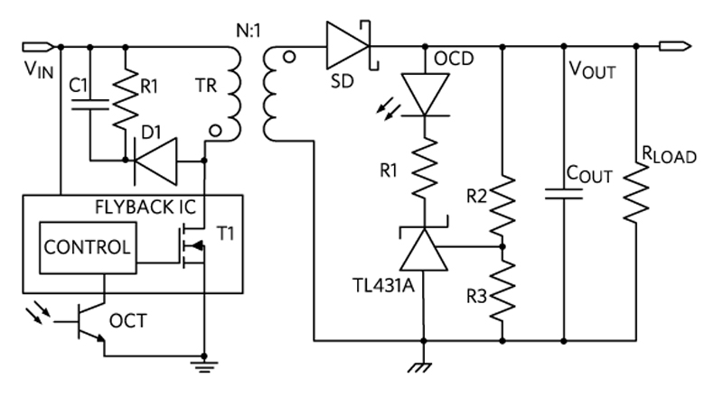
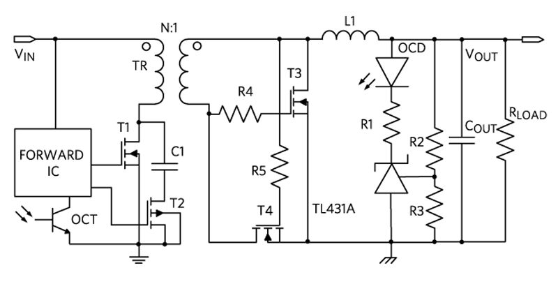
Industrial applications with switch-mode power supplies and isolated, step-down designs below 40W commonly use flyback and forward-converter topologies. To minimize the number of output components, the flyback converter (Figure 1) uses a gapped transformer to transfer as well as store energy. However, this type of converter is best suited to low-power applications because of the high peak currents inherent in its discontinuous operation. The forward converter (Figure 2) becomes a better option when power increases because the inductor following the transformer results in a smoother secondary side current.
![]()
Click image to enlarge
Fig 1: Flyback converter with integrated power transistor block diagram
Click image to enlarge
Fig 2: Active-clamp forward block diagram
Reference Designs Simplify Your Design
Maxim offers six 24V input reference designs that simplify the design of isolated power supplies. Supporting a range of industrial applications from 2W to 40W, these reference designs are ready to go right out of the box. They include bill of materials (BOMs), schematics, layout files, and Gerber files. Three are available with a flyback architecture and provide low current output. The other three use the active-clamp forward architecture. For fast transformer selection, every power rail is isolated with a readily available transformer from multiple global vendors. To learn more about the converter topologies and the reference designs—MAXREFDES111#, MAXREFDES112#, MAXREFDES113#, MAXREFDES114#, MAXREFDES115#, and MAXREFDES116#—read my article,
“Power Your Isolated System Effortlessly from 2W to 40W.”