Creating Smaller, More Efficient Isolated Power Supplies with Iso-Buck Converters

While isolated DC-DC voltage regulators are more complex than non-isolated variations, most design engineers still expect them to be highly efficient and fit into a small space. Let’s take a look at why isolation is useful in low-voltage power conversion systems and take a look at a novel isolated architecture that is more compact and power efficient than the classic flyback converter.
Protecting Sensitive Loads, Preserving Equipment Reliability
Input voltages below 60V are considered to be inherently safe to touch, according to SELV/FELV regulations. However, there’s still a pervasive need for isolation in this operating range. In this range, the power-supply electronic load, which is commonly a rather delicate and expensive microcontroller, needs to be protected. Otherwise, if it is inadvertently exposed to high voltages, the electronic load could self-destruct.
Isolation also guards against ground loops. Ground loops can product parasitic currents that could disrupt the output voltage regulation and also introduce galvanic corrosion of the conducting traces, degrading equipment reliability. When sensitive loads need to be protected and the long-term reliability of equipment preserved, you’ll likely see the use of isolated power supplies.
Low-Voltage Isolated Systems in an Automated Factory
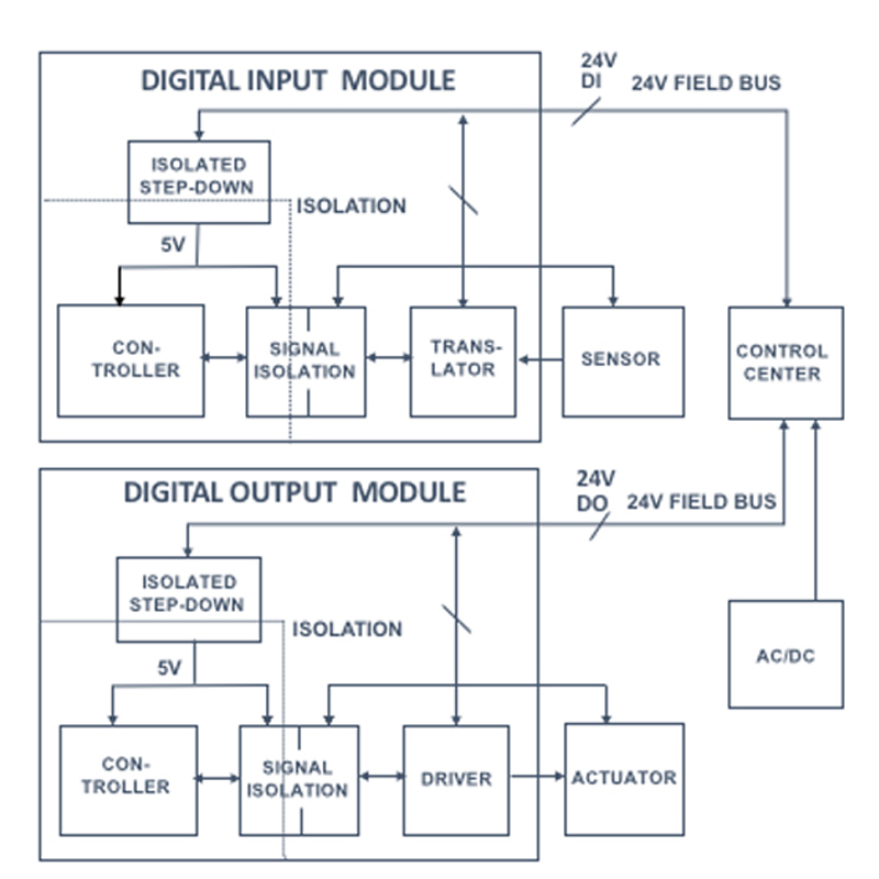
In an automated factory, I/O modules that are central to factory process control are a great example of low-voltage isolated systems. Figure 1 shows a block diagram of a digital I/O module and factory system. Here, a central hub takes the AC line power and converts it to 24V DC, delivering it to the I/O module together with the corresponding digital input (DI) and digital output (DO) data. The factory environment is harsh; sensitive electronics need protection from electric and magnetic interferences and over-voltages.
Click image to enlarge
Figure 1: Digital I/O module and factory system block diagram
For each module, the programmable logic controller (PLC) is powered by an isolated step-down voltage regulator. A rugged voltage-level translator interface at the digital input module (DIM) powers the sensor, receiving its information and passing it along to the PLC via a digital isolator or optocoupler. On the digital output module (DOM), a similar power, signal, and isolation chain leads to the on-board driver, interfacing to the external actuator. Modern systems call for a power-efficient and compact implementation of the isolated step-down converter in the input and output modules.
Flyback Converter vs. Iso-Buck Implementation
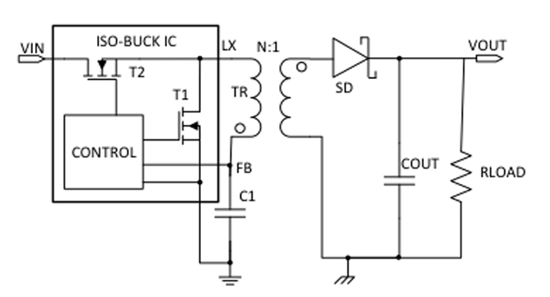
The flyback converter is a classic architecture that produces an isolated output. It features a rather complex control loop, which requires an additional voltage regulator to regulate the voltage at the output. An optocoupler can provide the isolated feedback needed to close the loop to the primary winding. However, since this solution uses two ICs and several passive components, it is generally costly, inefficient, and space consuming. An Iso-Buck converter, on the other hand, uses a new and highly integrated architecture that greatly reduces the bill of materials (BOM). See Figure 2 for a block diagram of the Iso-Buck converter architecture, which eliminates the need for an optocoupler while still remaining isolated. By eliminating many external components, the Iso-Buck architecture is more power- and cost-efficient compared to the flyback converter. By comparison, the Iso-Buck converter reduces the number of BOM components by up to 50% and yields board-space savings of up to 30%.
Click image to enlarge
Figure 2: Block diagram of Iso-Buck converter
For a deeper dive into Iso-Buck converters, read my article, Iso-Buck Converter Enables Smaller, More Efficient Isolated Power Supplies.