Increase Power Efficiency in Your Small IoT Designs

As smart, connected devices get smaller, addressing their battery management requirements becomes more challenging. You want to delight end users with long battery life and efficient charging, you need to minimize heat generation, and you’ve got to do it all in a very small space. When developing mobile and internet of things (IoT) electronic gadgets, be sure to take a closer look at the charging and fuel-gauging ICs at the center of every battery management system. The right ICs can make all the difference in helping you meet your power and size goals.
Typical Charger and Fuel Gauge System
Figure 1 shows a typical charger and fuel gauge system, along with two safeout low dropout regulators (SFLDO) that drive the system’s USB interface.
All active and passive components for the system diagram shown in Figure 1 are accounted for in the solution drawing of Figure 2.
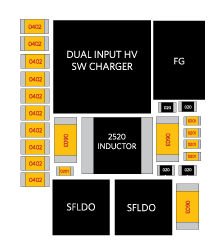
Figure 2. Typical Charger and Fuel Gauge System Footprint (55mm2)
From a space standpoint, the 1.5µH, 3.5A inductor (in a large 2520 package) and the two external LDOs in this typical implementation are problematic. This solution consumes about 55mm2 of board area.
PMIC Integrates Charger, Fuel Gauge, and LDOs
Figure 3 presents the MAX77818 PMIC, a single-chip solution that integrates the charger, fuel gauge with associated temperature sensing, and LDOs. With this approach, you don’t have the wasted space that’s associated with using multiple components. You can also use a lower value 0.47µH inductor that carries 3.5A in a smaller 2016 package. Compared to the typical charger and fuel gauge implementation just discussed, this integrated PMIC reduces space required by 33%, using only 37mm2 of total board space. The MAX77818 draws 20µA of total quiescent current, saving valuable battery life. Given this, you can either reduce your system size by using the smallest battery possible for your design, or allow longer use time between each charge.
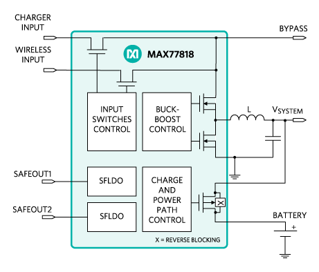
Figure 3. Highly Integrated Charger and Fuel Gauge System-on-Chip
We compared the efficiency of the MAX77818 with a competitive solution, powering both with a 1µH inductor in a 2520 package. The integrated PMIC exhibited higher efficiency across most of the load current range, even with a significantly higher switching frequency. Running at full load, the MAX77818 exhibited efficiency well above 88%, compared to just above 86% efficiency for the competitive product. Also, even with the large 2520 inductor, the integrated solution is 30% smaller than the competitive solution. Another plus of the integration of the MAX77818 is that it allows the fuel gauge and the charger to easily access the temperature, reducing silicon overhead and potentially lowering the thermistor count (no need to add a temperature sensor to the charger). There’s also less potential for PCB layout issues, since the fuel gauge and charger are in the same package.
You can read more about the key specs of the MAX77818 switching mode charger, and get details about its two evaluation kits.
.jpg)
Accelerating Isolated Power Supply Design
05/10/2017