
RF-to-Digital μModule receivers reduce size, cost & time-to-market
During my recent 3 week visit to California, I had the opportunity to visit Linear Technology. One of the major presentation highlights from this powerhouse of technology was made by Todd Nelson, Design Manager for Signal Chain Modules at Linear, and illustrated the new integrated ?Module® receivers, specifically designed for the receiver channel in cellular base stations, the LTM9004 and LTM9005. Building on its innovative ?Module technology, Linear Technology introduced the first RF-to-digital solutions with performance exceeding the demanding requirements of 3G base stations. Following the first RF-to-digital product, LTM9003 for base-station digital predistorion (DPD) applications, these new receivers integrate the RF mixer, gain stages, high-selectivity filter and 14-bit, 125Msps analog-to-digital converters (ADCs) in one package. The LTM9004 and LTM9005, two breakthrough RF-to-digital μModule® receivers that integrate the key components for 3G and 4G base station receivers (WCDMA, TD-SCDMA, LTE, etc.) and smart antenna WiMAX base stations. The integrated μModule receivers offer a dramatic reduction in board space, integrating the RF mixer/demodulator, amplifiers, passive filtering and 14-bit, 125Msps ADCs in one conveniently small package.
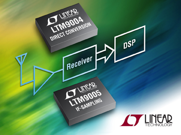
The LTM9004 implements a direct conversion architecture with an I/Q demodulator, low-pass filter and a dual ADC. The LTM9005 implements an IF-sampling architecture with a downconverting mixer, SAW filter and a single ADC. This high level of integration enables smaller boards or higher channel count systems, alleviating issues related to separation and routing of signals, while providing a significant reduction in design and debug time. These receivers harness years of signal chain design experience and offer it in an easy-to-use 22mm × 15mm μModule package. Cellular service providers are under intense pressure to reduce capital (CAPEX) and operating (OPEX) expenses. Supporting trends include the need for smaller, lighter, lower power base stations such as remote radio heads (RRH) that can be mounted on the tower with the antenna; and high density, high channel-count macrocell base stations with higher efficiency; and the use of small, digital repeaters. These μModule receivers address these trends directly. At only 25% of the board space area of discrete designs, the LTM9004 and LTM9005 save critical space and also reduce the time and effort required for optimizing the design and layout of dozens of high frequency components. This leads to lower development costs, fewer components to source and stock, and faster time to market. Two receiver architectures dominate base station designs: direct conversion and IF-sampling. Direct conversion demodulates the RF signal and downconverts to DC (0MHz in the frequency domain). This simplifies the filter, allowing low-pass filters with a 10MHz cutoff (20MHz signal bandwidth). The LTM9004 implements this architecture. Other filter options are available for different signal bandwidths. IF-sampling downconverts to an intermediate frequency (IF), 140MHz in this case, and the signal is demodulated in the digital domain. The 20MHz signal filtering is done with a surface acoustical wave (SAW) filter integrated in the LTM9005. Other filter bandwidths are available.
Deceptively Simple In concept, there are four elements to the LTM9004 and LTM9005: an RF mixer, an amplifier stage, a filter and a high-speed ADC. In practice, it is difficult to drive an ADC at this performance level, to filter the signal well enough to meet the 3G requirements, and interface to the mixer without introducing distortion. Typical discrete implementations use about 100 passive components. The routing of sensitive traces around the printed circuit board (PCB) takes tremendous care and multiple iterations in order to extract the maximum performance from these components. Even such simple components as bypass capacitors, which are integrated in the LTM9004 and LTM9005, can have tremendous impact on system performance. Inside the part, the capacitors sit close to the ADC supply and reference nodes, minimizing the distance to ground and thereby maximizing performance. Summary of Features: LTM9004 & LTM9005
- Fully Integrated RF-to-Digital Receivers for Base Station Applications
- 14-Bit, 125Msps Low Power ADC
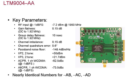
- Direct Conversion Architecture (LTM9004)
- 800MHz to 2.7GHz RF Input Range
- I/Q Demodulation & Dual ADC
- DC-Coupled, Fixed Gain, Fixed Cutoff LPF
- 5V & 3V Supplies, 1.8W Total Power Consumption
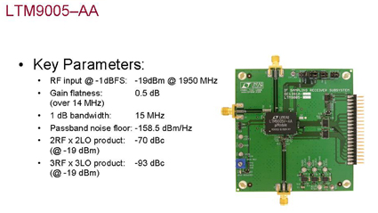
- IF-Sampling Architecture (LTM9005)
- 400MHz to 3.8GHz RF Input Range
- Continuous 20dB Attenuation Range
- 20MHz SAW Filter, 140MHz IF
- 3.3V Supply, 1.3W Total Power Consumption
- 22mm x 15mm LGA Package
The LTM9004 and LTM9005 are packaged in a space-saving 22mm x 15mm LGA package, utilizing a multilayer substrate that shields sensitive analog lines from the digital traces to minimize digital feedback. Supply and reference bypass capacitance is placed inside the μModule package, tightly coupled to the die, providing a space, cost and performance advantage over traditional packaging. As always with Linear, comprehensive and credible data sheets, demo boards and samples are available from www.linear.com or via a local Linear Technology sales office. www.linear.com/9004
