Power Semiconductors
December 2021
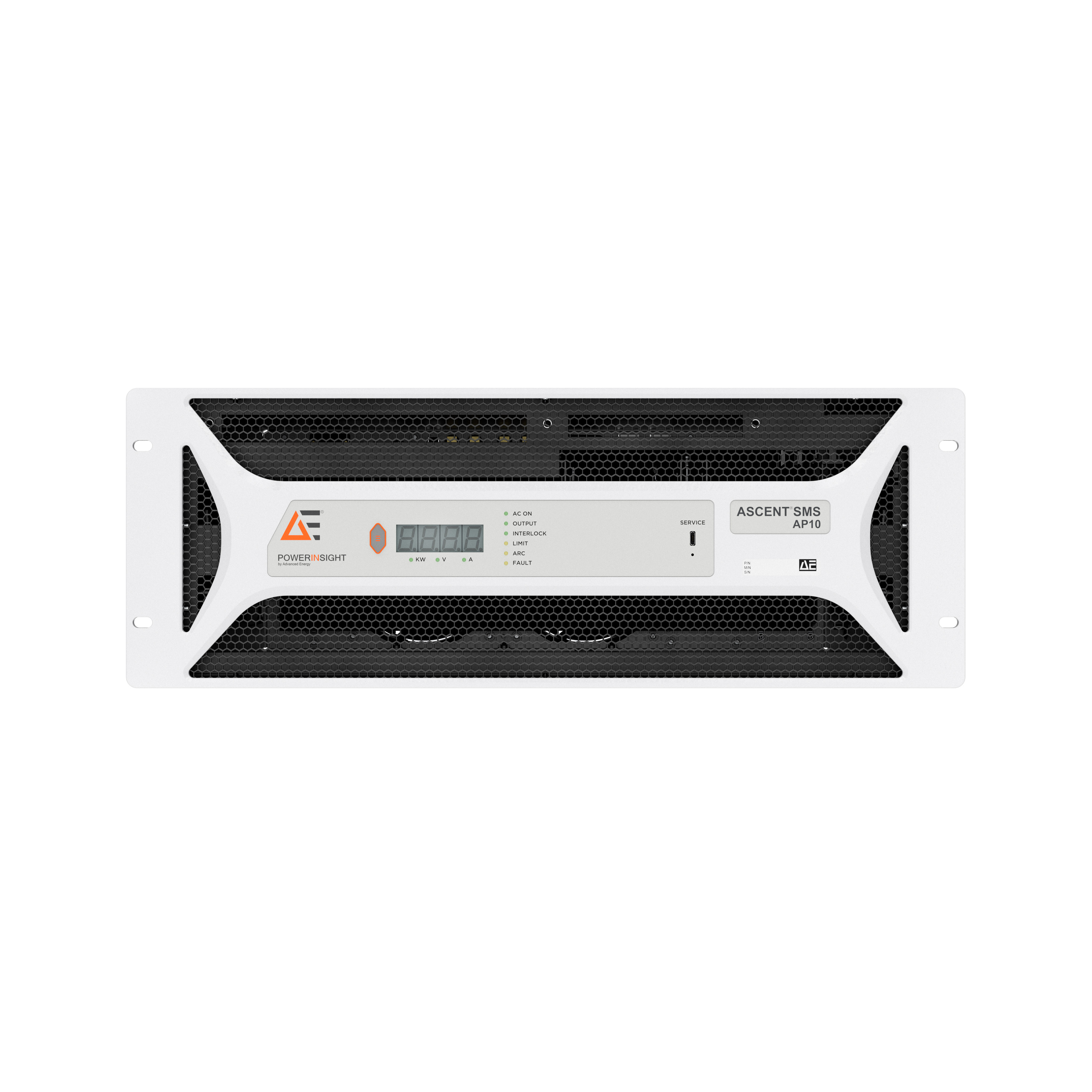
Advanced Energy has expanded its family of plasma power generators with a 10 kW pulsed DC power supply that combines industry-leading power and control capabilities with PowerInsight by Advanced Energy embedded process optimization software. With patented pulsing technology, the Ascent SMS AP (Advanced Pu
. . . Learn More
Date:
12/07/2021
Click image to enlarge
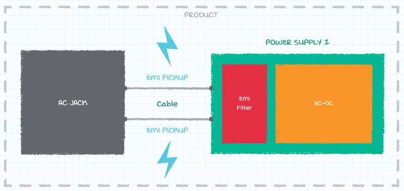
Figure 1: EMI pick-up in cabling
Among the most important of these specifications will be the ones that relate to electro-magnetic interference (EMI) and electro-magnetic compatibility (EMC). Having a good understanding of the EMI/EMC aspect of the chosen power supply will therefore be an essential part of its implementation. Furthermore, with bot
. . . Learn More
Date:
12/01/2021
Click image to enlarge
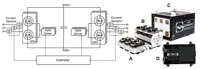
Figure 1: The system block diagram (left) showing three main components: the two converter modules, each with a gate driver, and the controller. The power modules mounted on the cold plate (A), and then in the power core with gate drivers (B), are also shown outside the dual inverter enclosure (C). Handles and feet are provided for portability, (D) shows the 204 mm x 267.5 mm cross section
The traction drive is where nearly all of an electric vehicle’s (EV’s) energy is put to use. The drive system must, therefore, perform with the highest possible efficiency while occupying the smallest possible space with the lowest weight — all to maximize the EV range. With the use of dual drives to enhance tr
. . . Learn More
Date:
12/01/2021
