1.5kW Digital Totem Pole PFC Design for Air-Conditioner Using iMOTION Digital Controller
Bridgeless totem pole PFC implementation eliminates EMI issues found in traditional boost PFCs
A lot of research focuses on bridgeless PFC in order to achieve higher system efficiency compared to traditional boost PFC. Most of the bridgeless PFC solutions suffer from EMI issues, which cause problems in applications where an inverter stage shares the same ground. In this case, the PFC stage generates a lot of noise to GND level especially at high-frequency operation.
The bridgeless totem pole PFC implementation does not have this problem and in combination with the development of fast IGBT and commercial availability of high bandgap switches such as SiC and GaN, this solution is seen as candidate to replace traditional boost PFC.
It is a matter of fact that designing a totem pole PFC requires a more complicated control circuit compared to a conventional boost PFC. However, most of the systems require higher efficiency by keeping the overall system cost as low as possible. So the challenge was to implement a totem pole PFC without using expensive sensors for AC voltage and inductor current sensing and to minimize the complexity of the control circuit.
The chosen solution uses a differential amplifier to do AC voltage sensing and uses single shunt resistor on DC link to sense inductor current. There is no additional hardware to detect AC voltage polarity. Digital control also makes it possible to re-construct the inductor current information from the single shunt on DC link.
Hardware Design
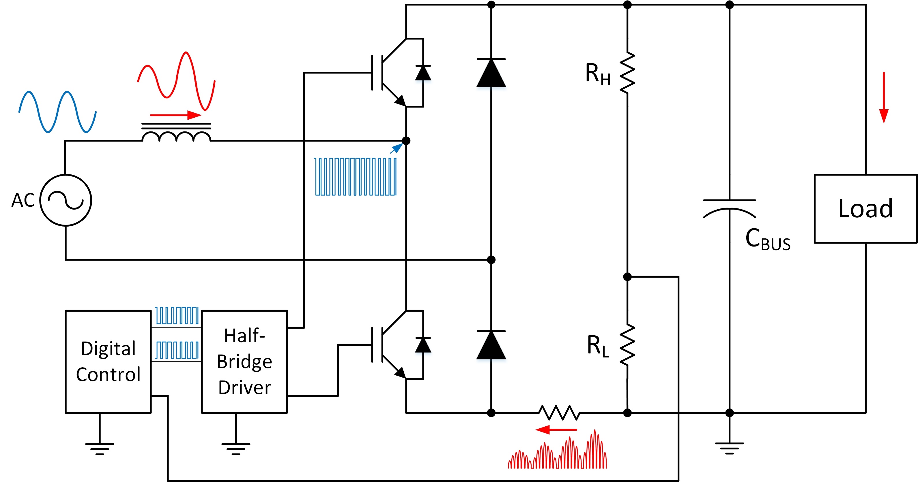
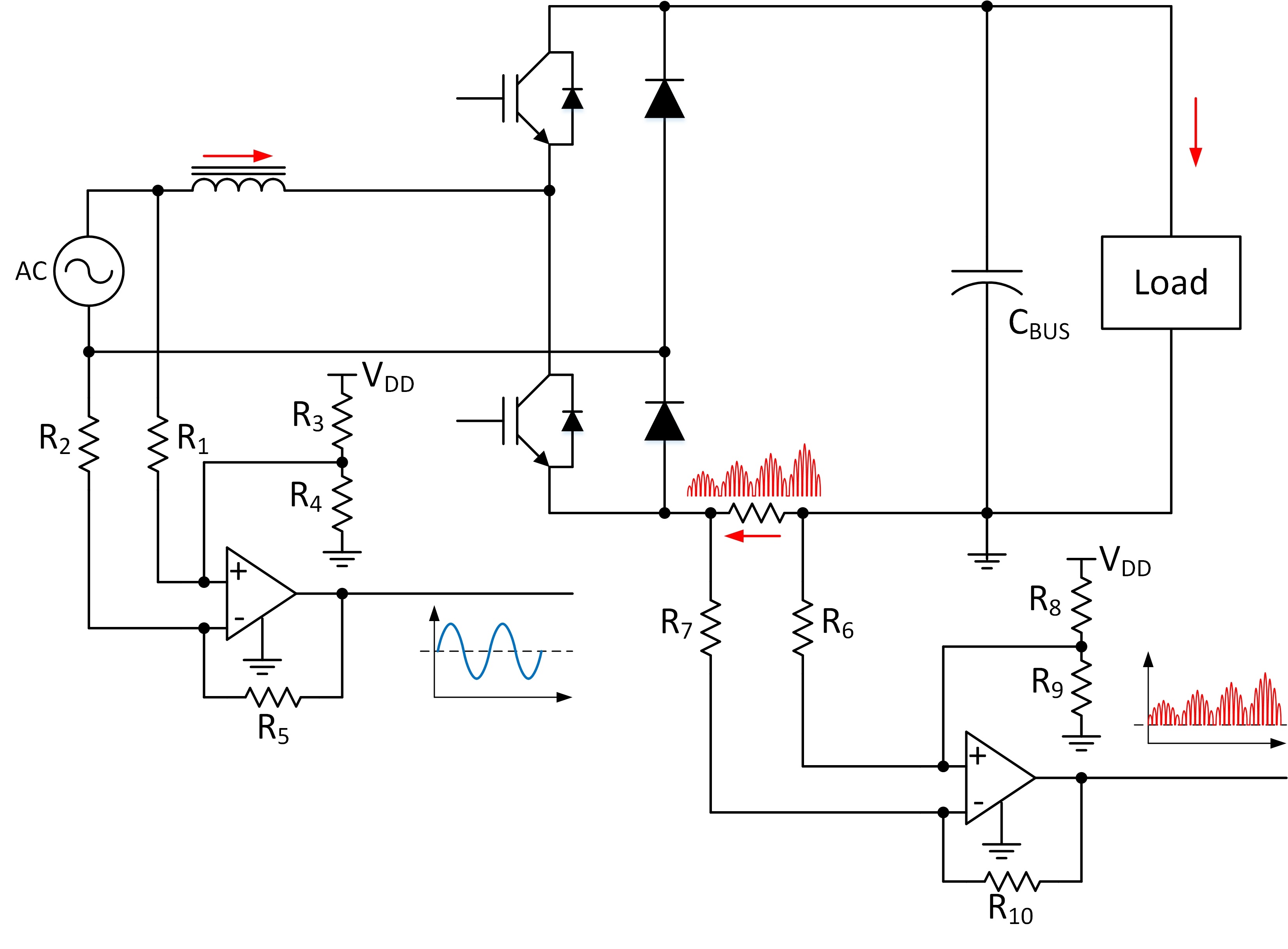
As illustrated in Figure 1, the implemented totem pole PFC uses only two switches in first phase, and it uses regular rectifying diodes in second phase. It is for sure possible to replace both diodes in the second phase with two additional MOSFETs to further improve system efficiency, but the efficiency gain is not big enough to justify extra hardware cost.
As Digital Controller Infineon’s IMC102T-F064 iMOTION Controller was used. This device is part of a family providing an easy implementation to run a PMSM motor with sensor-less FOC control. Additionally it integrates the digital control functionality for a totem pole & boost PFC. As MOSFET driver Infineon’s IR2114 half-bridge gate driver IC with integrated desaturation detection circuit is used. Both IC’s are on the same negative DC link ground which simplifies the auxiliary power supply.
The DC bus voltage sensing simply uses a resistor divider (RH and RL in Fig.1) fed into the analog input of the IMC102T-F064.
Click image to enlarge
Figure 2: AC voltage and inductor current sensing circuit
Two op-amps are used for AC voltage and inductor current sensing. Each of them is configured as a non-inverting differential amplifier. Output signal of zero input signals are biased in order to sense bi-directional signals. For AC voltage sensing, the biasing output voltage is set to the ½ of Vdd voltage. In this case, the resistor values of R3 and R4 are equal. For inductor current sensing, op-amp output is biased at ¼ of Vdd because the signal is mostly one-directional. The resistor value of R8 should be equal to R9*3.
Digital Controller - Functionality
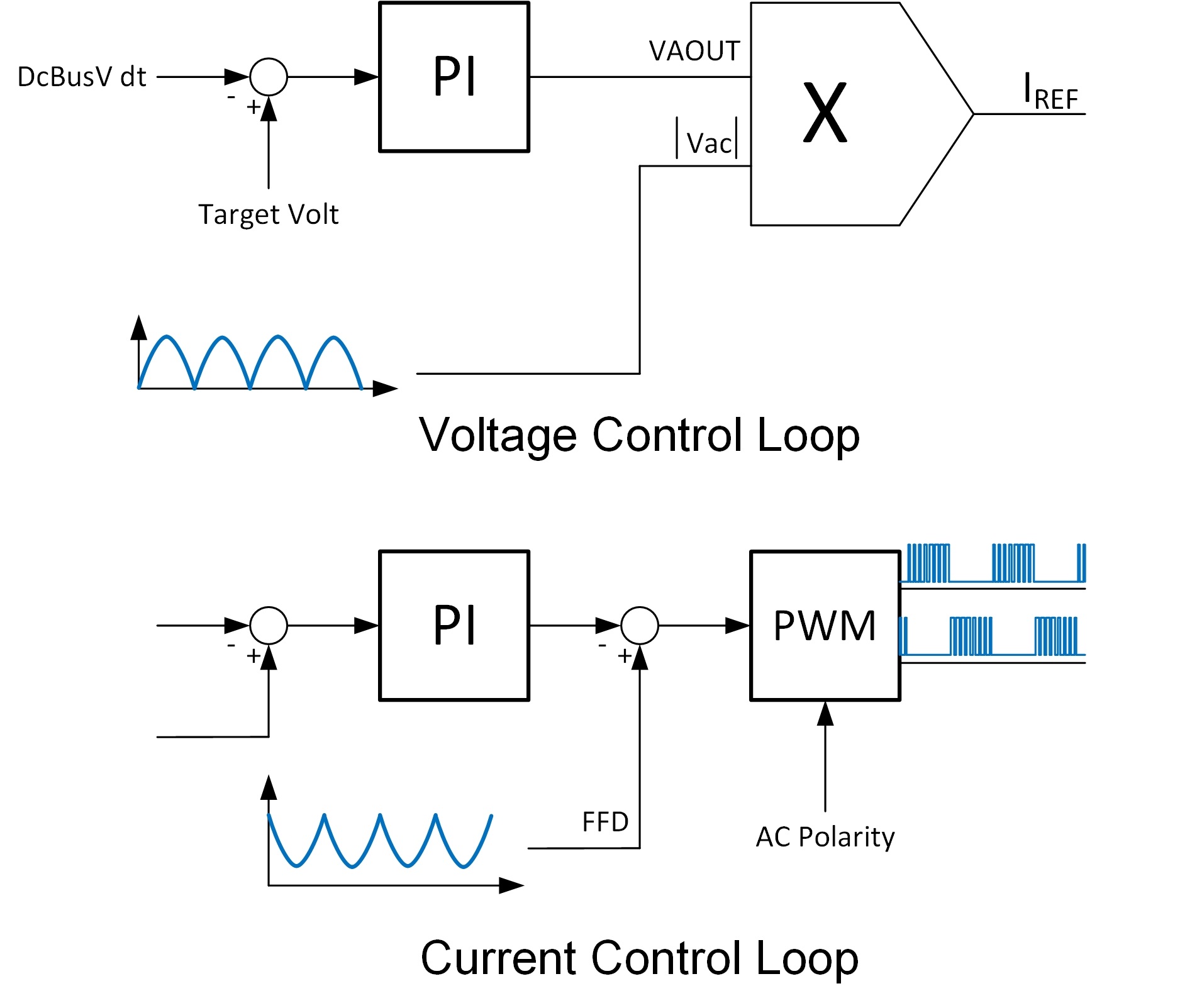
The PFC firmware of the IMC102T-F064 is comprised of several key function blocks: PFC current control loop, PFC voltage control loop, AC voltage sensing and inductor current sensing. The PFC Control Loop consist of: voltage control loop as outer loop and current control loop as inner loop.
Voltage control loop is comprised of voltage PI regulator that outputs the voltage error signal “VAOUT”, and a multiplier that multiplies the voltage error signal with the rectified AC voltage signal “|Vac|”. The output of the multiplier is the current reference that will feed into the inner control loop. Because of the low bandwidth of the voltage control loop (usually <10Hz), the voltage PI regulator is executed every 1ms.
The current control loop is comprised of a current PI regulator, PWM module and feed-forward signal injection. The Feed-forward signal is added to the output of PI regulator to reduce the burden on the current PI regulator.
AC Voltage information is used to perform various tasks. The multiplier based PFC needs the AC voltage signal to shape the current reference for the current regulator. The output of the optimized integrated ADC is used to directly generate IREF, without the need of lookup tables or hardware vector rotator.
Click image to enlarge
Figure 3: PFC control loops
The IMC102T-F064 is using several techniques to detect polarity and zero-crossing, such as: inserting a blanking time for zero-crossing checking after having detected a zero-crossing event, positive and negative half cycle time balancing check, zero-crossing delay compensation.
To protect the PFC stage some abnormal conditions are detected: AC over-voltage, AC under-voltage, AC frequency out-of-range, un-balanced AC voltage and voltage sag. In addition, some housekeeping tasks like RMS voltage calculation and AC offset measurement and self-correction are performed.
DC Link Shunt Resistor Inductor Current Sensing
Using the DC link shunt resistor for inductor current sensing has the lowest system cost. The main drawback of this sensing mechanism is, that the shunt resistor only carries the inductor current signal during freewheeling (when switches are off and the current is freewheeling through the diodes).
It’s impossible to sense the inductor current while the switches are on, so the PWM turn on duty cycle has to be limited in order to allow for a current sensing window.
PFC Inductor current is sensed after the PWM signal is switched off with a short delay time. The benefit of this sensing mechanism is that the sensing point doesn’t need to be changed by different duty cycle. This sensing mechanism is equivalent to peak current sensing, resulting in higher THD compared to average current sensing. For better THD performance, some software adjustment to sense the peak current may be necessary.
Click image to enlarge
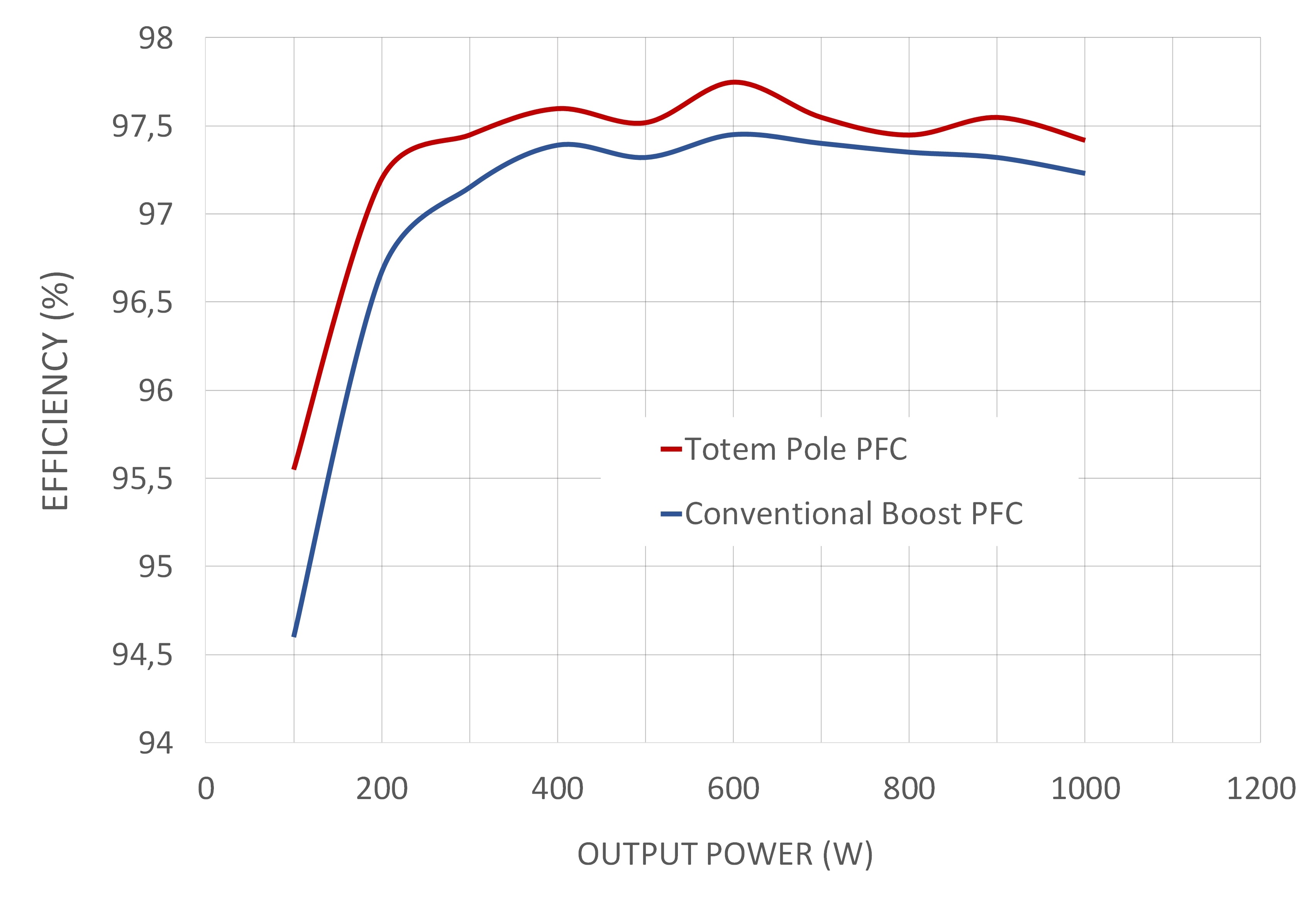
Figure 4: Efficiency Totem Pole vs Boost: Efficiency Comparison (Totem Pole vs Boost): Test condition: Input: 220Vrms, Output: 400Vdc, Switches: IKA15N65F5 IGBT, Rg: 200Ω, Fpwm: 50kHz, Inductor: 1mH ferrite
Test Result
EMI Comparison (Totem Pole vs Boost): Performed Conductive EMI measurements have shown no difference between a traditional boost and the totem pole topology described above.
Figure 4 shows ~0.3% gain in efficiency with the totem pole topology. This test was performed with a 200Ω gate resistance, which is not optimized to reach the best possible efficiency. The goal of this test was to show the efficiency difference between totem pole and traditional boost topology and not the absolute efficiency numbers. The efficiency difference is expected to be larger with lower AC input voltage.
Infineon