A novel power module concept for the low-voltage MW class
Renewable energy and high-power MW drives demand reliable power module concepts
Various applications such as renewable energy generation and high power drives in the MW range have an increasing demand for high reliable power module concepts addressing the operation in a harsh environment. Next generation designs e.g. of wind turbine inverters need to be more reliable, more compact and less expensive to bring down the costs of installation and operation.
Actual low voltage designs have reached their limits for current capability, weight and size. For example, SEMIKRON has introduced the SKiN technology as next generation assembly technology of power electronics after a long advanced development phase. SKiiP X is is a modular, highly compact low voltage IPM overcoming today restrictions of 2MW+ applications.
A primary failure root cause in wind and other demanding applications are pollution and condensation. The SKiiP X is the first product on the market especially designed for climate class 3K4 and explicitly withstanding condensation in the system by allowing pollution degree 3.
The Design Concept
The power ratings of MW drives in wind applications increase step by step. By increasing the power to 6000amps the size and weight of the inverter has to be reduced by half. The need for compact systems, high reliability and low cost means that new technology approaches are demanded and the classical modules used in power electronics – with copper base plate, solder joints, module case and wire bonding - will gradually vanish from the market.
Today high power inverters in the MW range are based on parallelization of modules and/or inverters resulting in the cost increase by reducing the overall reliability. Redundancy concepts are an option to achieve the requested high system availability but only with the disadvantage of high initial investments.
The maximum permissible power dissipation of a power semiconductor is limited by the maximum junction temperature, the temperature of the cooling medium, and the thermal resistance between chip and cooling medium. A watercooler based high performance electronic power system shows in its thermal model that thermal paste is a key influencing variable and makes up for approximately 30% of the overall systems thermal resistance. By sintering the DCB directly onto the heat sink, this shortcoming can be eliminated. Bringing base plate materials into a liquid cooling circuit one has to be extremely careful about the long term corrosion effects.
Cooling media and base plate material/coating have to match sufficiently. Therefore aluminum is the preferred choice due to its self-passivation (natural aluminum oxide) when liquids contain a small amount of oxygen. The dilemma is that it is not the preferred choice for base plates because of its high CTE and its poor compatibility to soldering. However, there are ways to solve these challenges: The usage of silver diffusion sintering to attach a pure Aluminum small area pin fin cooler to a DBC substrate.
A comparison of the thermal resistances of a conventional layered system with base plate and SKiN technology shows that the thermal resistance between the IGBT junction temperature and the temperature of the cooling liquid comes down by 30%. A welded joint to the capacitor or the DC link allows a cost efficient, compact and reliable interface.
Today most coolers are arranged on the same level as the main assembly direction of modules and bus bars. The small SKiN units allow different design approach. Three SKiN elements are mounted onto a common liquid cooler. The resulting base element builds the core of a so called “power blade” and allows practical use of all SKiN technology advantages, like low stray-inductance, optimal cooling and very compact design.
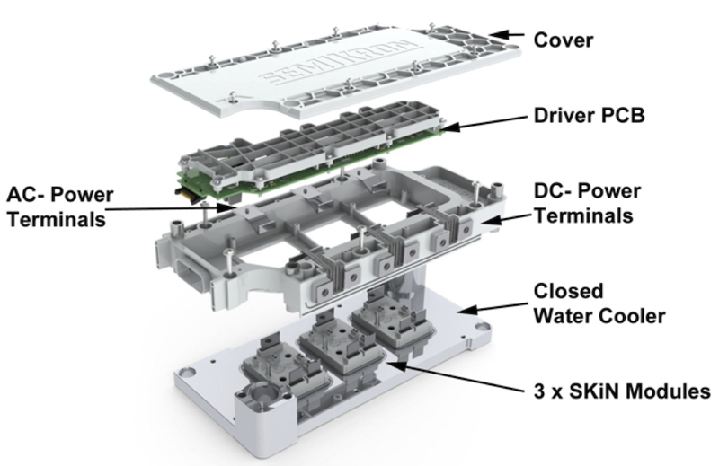
To build up a module, interfaces to DC-link and AC-output, driver functionalities and cooling have to be added. Figure 1 shows a power blade, able to deliver 540 amps at a size of approx. 260 x 115 x 45 mm. Despite an integrated water channel, the cooler design separates electrical and fluidal areas even in fault conditions. Diagonal liquid flow allows autonomous venting at multiple default mounting positions without additional measures. Optimization of the flow area shape and the pressure-drop ratio results in harmonized volume streams even in a nine-blade configuration by a total pressure drop less than 400mbar.
Click image to enlarge
Fig. 1. Explosion view of a SKiiPX power blade
Mechanical considerations
Beside cooling, the liquid cooler with its three power modules acts as robust mechanical basis for the blade, too. A plastic frame on top of the cooler fastens the inserted power terminals, which are molded by an elastomer, which provides necessary sealing between environment and inner space. DC-link and AC-out terminals are located opposite at the blade’s long sides as shown in Figure 1. For a smooth switching behavior the internal and external stray inductances are kept very low.
To prevent higher noise levels on the switching signal the coupling of the main current circuit to the auxiliary circuit has to be low. The existing SKiN design achieves stray inductances in the area of 4 to 5nH, with terminals up to 15nH. A close parallel operation of two modules reduces the stray inductance compared to module designs with bus bars by at least 50% and is a good precondition for a superior current sharing.
The secondary-side driver board is fixated by the plastic frame, too. Thermally sensitive electronic parts are closely attached to the cooler to extend their lifetime. On top of the blade a flat plastic sheet covers the inner structure and seals it against environmental impacts.
Basically the overall system consists of multiple blades stacked on top of each other plus two end parts. Those are providing water inlet/outlet as well as mounting functionality. One essential idea of SKiiP X concept is to use identical power blades regardless of the overall system configurations, e. g. paralleled half-bridges or 3-phase configurations.
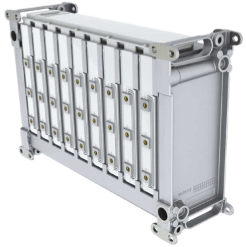
Figure 2 shows a complete SKiiP X system consisting of nine power blades including the top sided interface plane to the controller as well as AC-outlets at the front side. Climate protection has been increased to climate class 3K4 and pollution degree 3 supporting long life operation in harsh environments. Compared to SKiiP® 3 (launched to the market in 2000) the footprint area has been reduced by 70% for the same achievable output power which leads to a significant reduction of the inverter size.
Click image to enlarge
Fig.2: SkiiPX System assembly with nine blades for a 1.5MW 3-phase configuration.
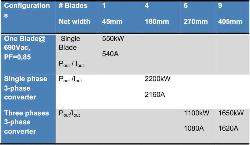
Table 1 shows several IPM configurations. The largest 3-phase type, consisting of nine blades, is able to handle 1650kW power and is mountable in an 600mm cabinet. This scalability supports versatile cabinet and power configurations. Weight of a 9-blade configuration is targeted below 25kg.
Click image to enlarge
Table 1: shows several IPM configurations
Using the 9-blade version in a stack configuration each of the three AC-out bus bars are collecting the AC outputs of 3 blades. An appropriate current sensor can be easily attached externally to them. Five of this units can be mounted into a 600mm wide cabinet at standard height of 2000mm building a four-quadrant 3.3MW inverter plus brake chopper unit. Today systems need approximately twice the space
Gate driver and performance
Each power blade includes its own 2nd side driver, fully insolated to the primary side. The driver board within each blade provides sufficient power to drive the paralleled IGBT gates of all three blade power modules. The the logic interface connector at the blade front side uses voltages below 30volts while the overall jitter remains below 10ns.
Double pulse test switching up to two times of Ic nominal (1100amps) for one blade shows a very good behavior in terms of current sharing, switching behavior and transient overvoltage. The overall rising current mismatch remains always below 10%. The important variance of switching delays does not exceed 50ns while transient overvoltage stays at any time below 1700volts @ 1300volts DC-Link voltage. This is valid for the whole operation temperature range without additional snubber capacitor.
The new assembly concepts sets a benchmark for reliability. SKiN ® Technology increases the power cycling capability by a factor 10 compared to traditional soldered and bonded modules thanks to the low temperature diffusion sintering attach. Part count of driver components is reduced by 50% as well the number of critical electrical plugs and water connections. Compared to e. g. SKiiP® 3 based assemblies the fit rate is decreased by half.
SKiN®-technology is a revolutionary progress in technology. It combines a reduction of low thermal resistance and reduced internal parasitic inductance and enhanced reliability of a wire bond free package technology platform. However in order to exploit the advantages emerging from this new technology, the module outline and system configuration are different to this new packaging platform.
A novel design approach using a 500kW building block for use in low voltage converters shows that twice the current density can be achieved compared to a solution based on standard modules. Regulatory requirements in wind inverter applications have demanding requirements for the grid support like voltage and low frequency ride through conditions. The power module has to support these conditions by ability to work in an overload or high voltage situation. The new concept opens the 6MW+ market for low voltage inverter using all the known benefits in terms of less restrictions and lower costs compared to medium voltage systems.
References
[1] P. Beckedahl et al.: Performance comparison of traditional packaging technologies to a novel bond wireless all sintered module; PCIM Europe 2011


