Behind-the-scenes power management is vital to achieving reliable, effective operation
There’s a large element of irony in the design of today’s cars. They are increasingly energy efficient, yet they also have many more electrical demands being placed on them. These demands range from an array of safety-related functions to numerous in-cabin convenience, connectivity, and entertainment features, such as basic AM/FM radio, satellite radio, multimedia systems interface, GPS, cellular support, Bluetooth®, Internet/Wi-Fi®, and much more.
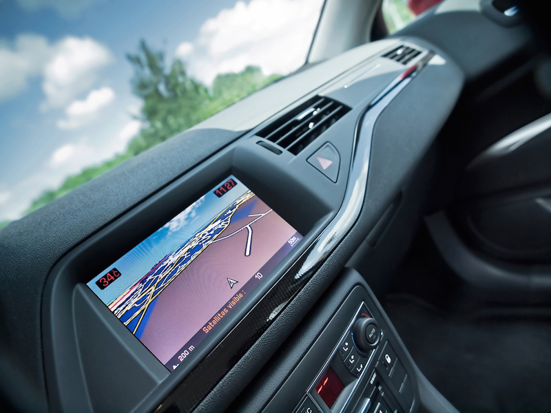
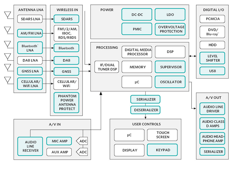
The location of many of these electronic subsystems is known as the “radio head unit” (see Figure 1). It is the central part of the user console and instrument cluster where the various displays, signal routing functions, user interface, and internal electronics are actually located or their paths converge (see Figure 2). There can be as many as eight to 10 major subsystems packed into this compartment. As a consequence, it’s a critical location for providing multiple DC-power rails and dealing with heat dissipation.
Click image to enlarge
Figure 1. Behind the visible auto console is a complex interconnection of circuitry and systems, all of which require substantial DC power and support by sophisticated power management
Click image to enlarge
Figure 2. This block diagram gives a general indication of the number of complex functions supported by the auto radio head unit behind the console
The head unit power challenge
As with many complex subsystems, the head unit design must balance conflicting power demands and constraints. On one side, there’s the need for providing well-regulated voltages at various currents for the processors, memories, displays, and more. These DC/DC regulators must be efficient, to minimize the associated temperature rise due to the power subsystem, for both the sake of the regulators themselves and the electronics they support. Many of these regulators must also be efficient when providing just a few milliamps needed to keep critical circuits alive (keyless entry, clock, alarms, and some memory functions). This is especially critical when the car is nominally “off” for days and even weeks, so the car battery doesn’t discharge below the capacity needed to start next time.
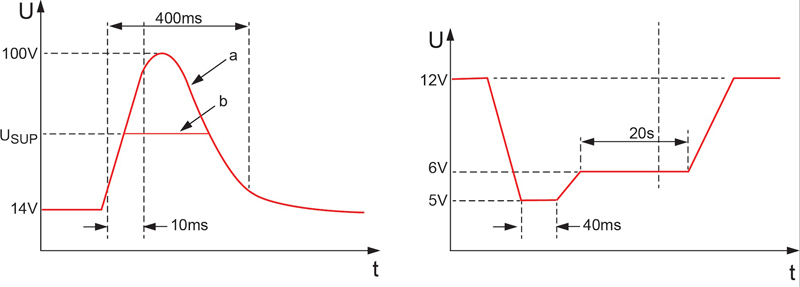
Adding to these basic challenges is the automobile’s electrical and thermal environment. Although, in principle, the vehicle is battery powered and thus has a stable and quiet DC source, the reality is quite different. The basic DC rail of the car is noisy, with large and sudden drops when starting the car (cold cranking), which can drop the rail to half its nominal value. At the other extreme, the rail can spike when loads are suddenly removed (called “load dump”) causing transients as high as 42V (see Figure 3)
Click image to enlarge
Figure 3. The nominal 12VDC battery supply is actually a complex and somewhat hostile electrical rail, as shown by these voltage-vs.-time characterizations of a) load-dump surge, and b) cold-crank voltage
Thus, the nominal 12.6VDC with moderately tight tolerance normally supplied by a standard lead-acid battery actually has wide static and dynamic swings. This further complicates the design of the regulation function. As a result, the regulation circuitry must be designed to resist the effects of these transients, and even function despite them.
There’s another consideration in the harsh auto environment: electromagnetic interference (EMI). With so much RF electrical noise in the car—some of it sourced internally, some of it from external environment—any electronic functions, including the power subsystem, must meet strict requirements on the maximum generated EMI (magnitude and spectrum) it generates, as well as susceptibility to pervasive EMI around it.
In addition to these well-known issues with the auto’s basic power rail, there’s a new twist: the increasing use of “start-stop mode” for the gasoline engine vehicles to increase gas mileage. Shutting the engine off at stop signs, red lights, and similar situations, and then restarting it within a fraction of a second when the driver steps on the gas pedal, minimizes idling gas consumption. However, it also repeatedly stresses the electrical system with load dumps and transients each time the vehicle is stopped and restarted, which can be frequent in stop-and-go traffic.
As if these realities aren’t enough to worry about, overlying all these electronic issues is a major nonelectrical but intimately related concern: the thermal environment of the head unit. It must function with outside temperatures as high as +85°C (185°F), and up to +105°C (220°F) internally. It’s a two-pronged problem: the heat that the regulators generate contributes to the head-unit’s overall thermal load (bad for the other circuits in the unit), while the regulators themselves must function within specification at the high temperatures.
Approaching the problem
Designers have resorted to a multifaceted approach to provide various supply rails, which the head unit must provide for the functions that converge there. The most obvious way is to use multiple automotive-compatible linear and switching DC-DC regulators, with one for each DC power rail needed.
While this works, it requires skill in selecting a suitable linear or switching regulator IC for each rail and ensuring that it meets requirements, then packaging the full set of regulators within the confines of the head unit’s circuit-board space. Depending on the frequencies used in switching regulators, there can be serious EMI and interference consequences of frequency mixing (heterodyning), yielding unexpected performance problems.
A better approach is to use highly integrated power-management ICs (PMICs) such as the Maxim MAX16993 or MAX16930, which provide multiple DC rails and are designed from the start for the auto environment:
• The MAX16993 (see Figure 4) is a multirail DC-DC regulator that provides three outputs in a single, small package. It has one high-voltage step-down controller (OUT1), which is designed to run directly from a car battery, plus two low-voltage step-down converters (OUT2/OUT3) that cascade from OUT1, each providing up to 3A output current with integrated FETs. The low-voltage outputs can range between 0.8V to 3.95V as fixed-voltage outputs or user-adjustable with resistor-dividers.
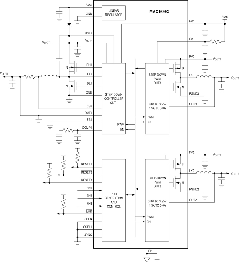
Click image to enlarge
Figure 4. The Maxim MAX16993 DC-DC step-down power controller provides one higher-voltage output and two lower-voltage outputs, specifically optimized in performance and capability for automotive situations
• The MAX16930 (see Figure 5) also provides three outputs: two high-voltage step-down controllers designed to run directly from the car battery, and a preboost on the front-end to ensure the system operates during cold crank events. These outputs can be adjusted between 1V and 10V. The preboost controller is enabled when the car battery falls below a user-selectable level, and is capable of keeping the system operating with car battery voltages as low as 2V.
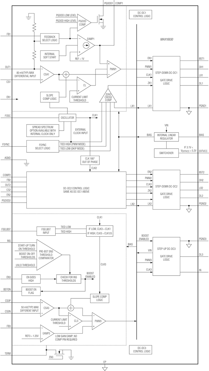
Click image to enlarge
Figure 5. The MAX16930 also provides three outputs, including a preboost for one regulator to ensure that the system operates during cold-crank events, when the rail voltage can drop as low as 2V
The high-voltage input controllers of these ICs can operate from battery voltages as high as 36V, and can tolerate load-dump transients up to 42V. Under no-load conditions, the MAX16930 consumes only 20μA of quiescent current while the MAX16993 consumes only 30μA, making them good fit for “sleep” automotive modes. Both high-voltage controllers are designed to operate with switching frequencies of 2MHz to eliminate AM-band EMI issues and minimize external component size. The switching frequency can be set to as low as 200kHz if desired.
To address critical EMI issues, both the MAX16930 and MAX16993 provide a user-selectable spread-spectrum function, which provides significant improvement in peak EMI levels. They do this by spreading spurious energy across a wider band while also lowering its magnitude throughout the band. In addition, the design of these components deliberately slows down the rise/fall rates of switching waveforms, which greatly reduces generated EMI, even though it sacrifices some efficiency. This balance provides an acceptable trade-off between the two conflicting requirements, since the EMI mandate is often harder to meet than the efficiency requirement.
To meet the user’s board-mounting preferences, the devices are available in two packages, TQFN-EP and side-wettable QFNDEP versions. The MAX16930 has a 6mm × 6mm outline, while the MAX16993 is in a 5mm × 5mm package. They incorporate both overtemperature and short-circuit protection, and are specified over a -40°C to +125°C operating temperature range. Maxim achieved this overall performance through a combination of innovative design and improved topology, supported by a high-voltage, high-frequency semiconductor process with low quiescent current (IQ).
These ICs provide superior cost and performance alternatives to “piecemeal” solutions pulled together from disparate regulator ICs. They minimize the difficulties for designers working to meet the difficult and increasing efficiency, reliability, and EMI demands on the automotive supply rail in the electronics radio head unit. (One other topology, called the point-of-load (PoL) approach, may seem a viable alternative, but it has serious drawbacks in overall performance and system-level reliability.) The highly integrated devices solve the problem effectively, while minimizing design headaches and trade-off penalties.
Figure 5. The MAX16930 also provides three outputs, including a preboost for one regulator to ensure that the system operates during cold-crank events, when the rail voltage can drop as low
as 2V