These days, much of the news coverage and discussion in the semiconductor industry is about devices based on the new wide bandgap (WBG) materials such as silicon carbide (SiC) and gallium nitride (GaN)
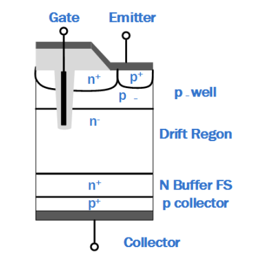
Figure 1: Field Trench Stop IGBT Structure
The medium-to-high power applications that used IGBTs still exist, as do the devices themselves. In this article we will take a detailed look at IGBTs and then consider existing and emerging topologies that they are suitable for.
IGBTs: Physical Structure
An IGBT is a semiconductor transistor, or semiconductor switch that is constructed with four alternating layers of semiconductor material (P-N-P-N). When the correct voltage is applied to the gate of the device that it is able to conduct current – when this voltage is removed, conduction is halted.
Since their inception, IGBTs have been honed and improved, especially with regard to improving switching losses as well as creating thinner structures. Nowadays, IGBTs often combine a trench gate with a field stop structure as a means of suppressing parasitic NPN characteristics within the device. Once this is achieved, the conduction losses and saturation voltage are reduced which brings benefits such as enhanced power density.
Examples of IGBT Use and Techniques
IGBTs are used in a wide variety of applications including solar inverter, energy storage system, uninterruptible power supply (UPS), motor drives, electric vehicle charger and industrial welding as well as in domestic appliances. Often the topology is chosen specifically to meet the needs of a particular application, so we will compare and contrast a few popular applications.
Industrial Welding
Given the need for higher-quality welds, there is a need for the welding process to be controlled with greater accuracy. For this reason, it is common to use an inverter rather than a typical welding transformer as a DC output current can achieve the necessary accuracy.
There is also a safety aspect to this as DC currents are generally considered safer. From a user perspective, the inverter is smaller and lighter than the transformer, so the resulting welder is more portable and convenient to use.
In a typical welder, the AC mains, single or three-phase, is rectified to form a DC bus voltage. The rectifier also powers a small converter that generates the voltage(s) needed for the control unit. The DC bus voltage powers the inverter which will normally have a nominal output voltage of around 30 VDC. However, during use, this can double under open load operations and collapse to almost 0 V (effectively a short circuit) as welding arcs are being struck.
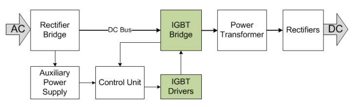
Click image to enlarge
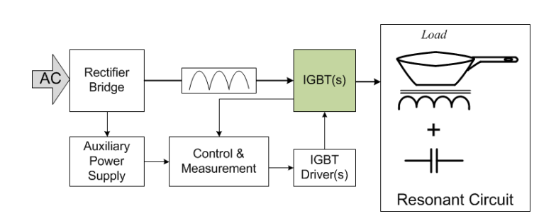
Figure 2: Overview of a typical welding machine
A number of different topologies are suitable for use in inverter-based welders. However, the most common include full-bridge (FB), half-bridge (HB), and double-switch forward. In FB and HB topologies, the switching frequency is tens of kilohertz, normally in the range of 20 – 50 kHz. The duty cycle is controlled based upon the load level and output voltage. In terms of the control scheme, this is usually constant current.
Click image to enlarge
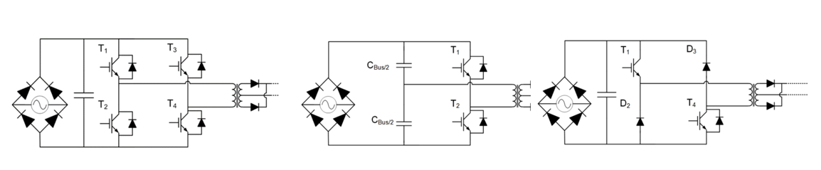
Figure 3: Common topologies include FB, HB and double-switch forward
Industrial Motor Drives
One of the most common industrial applications is industrial motor drives that may be used in robotics, large machinery or many other applications where motion is required. Most motor drive applications are configured as HB at a frequency between 2 kHz and 15 kHz. The output voltage from this depends on the switching state and current polarity.
Click image to enlarge
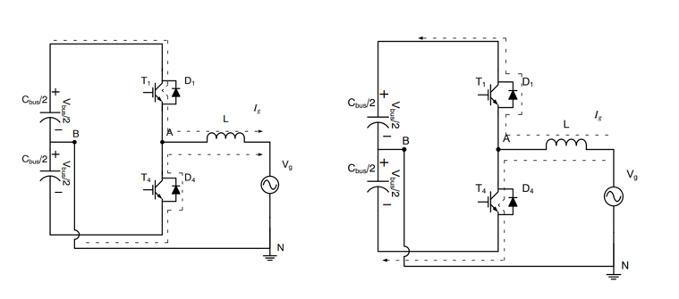
Figure 4: Half-Bridge topology showing positive and negative output current flow
Motors are an inductive load, so the current increases rapidly. When a positive current flows (Ig>0), the high-side transistor (T1) will conduct, delivering energy to the load (Vg). However, if the load current Ig flows in the other direction (negative polarity) the current flows back via D1, returning energy to the DC source.
If the low-side transistor is conducting (T4 is on) and the high-side transistor (T1) is off, then a voltage equal to minus half of Vbus (-Vbus/2) is applied to the load, decreasing the current flow. If Ig is greater than zero, the current flows through D4 returning energy to the bus source.
Modern Induction Stoves
Replacing traditional electric heating elements that get hot and transfer thermal energy to a saucepan / pot, induction stove cooking uses the principle of exciting a coil of wire to force, or couple, current to circulate within the base of the pot. For induction cooking to work, the base of the pot has to be physically close to the coil and only certain metals are suitable - a material with high magnetic permeability is required.
The theory is similar to a common power transformer with the coil being the primary, and the base of the pot being the secondary. It also has much in common with modern inductive charging technologies.
The heat needed to warm the pot comes from the circulation of eddy currents in the bottom layer of the pot or, more specifically, resistance to these currents flowing. Using inductive coupling, around 90% of the energy is transferred for the creation of heat in the pot. A typical smooth top non-inductive stove would only transfer around 70% of the energy, so the losses are reduced by a factor of three.
The topology used is not too dissimilar to the welding circuit. The mains AC is rectified to drive the inverter and a small auxiliary power supply for the controller. The inverter induces a current into the copper coil, thereby generating an electromagnetic field that induces the Eddy currents in the pot. The heat generated is equal to the electrical resistance of the pot base, multiplied by the square of the induced current – known as the ‘Joule effect’.
Click image to enlarge
Figure 5: Overview of a typical induction stove circuit
Unlike welding machines, the control scheme for induction stoves is often a variable frequency scheme. While this is a simple approach, the challenge lies in the range of frequencies required to control output power over a wide range.
Resonant converters can operate at high efficiency, even at the high frequencies that inductive stoves require. Therefore, resonant tank-based converters are commonly used in this application – especially resonant half-bridge (RHB) converters and quasi-resonant (QR) inverters. RHB converters are particularly valued due to the wide load range they can handle. Often, advanced control techniques such as zero current switching (ZCS) or zero voltage switching (ZVS) are used to ensure power losses are kept to a minimum.
Click image to enlarge
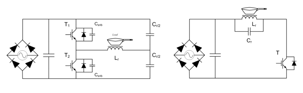
Figure 6: Examples of typical RHB and QR topologies
QR converters are frequently used in low-power (sub-2 W peak power) inductive stove applications due to the cost-effectiveness of this topology.
Solar Inverter and UPS
There are a number of challenges when using the half-bridge topology in applications that require fast switching including:
• Only possible to have two output voltages
• Switching losses can be significant
• Driving the gate can be challenging
• Component stress impacts reliability
• Increased ripple current and EMI requires significant filtering
• Incompatible with HV DC bus
• Thermal design is not trivial
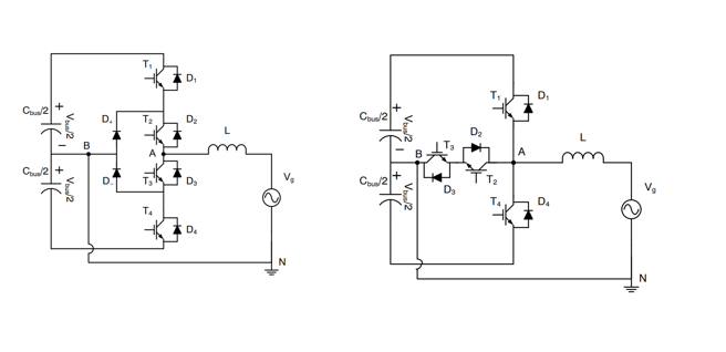
In modern applications, the HB topology is being replaced in key applications such as uninterruptible power supplies (UPS) and solar photovoltaic (PV) inverters. Three-level topologies are becoming dominant – known as I-Type and T-Type.
There are many areas of improvement including a reduction in the voltage across active components that lowers losses, reduces harmonic distortion and allows for the use of smaller components. Most importantly, these topologies enable significant reduction in switching losses, allowing efficiencies as high as 98% region while switching at high frequencies 16 kHz to 40 kHz.
Click image to enlarge
Figure 7: I-Type and T-Type converter topologies offer a number of benefits over HB
Looking Forward…
While some may see IGBT as a ‘legacy’ technology, it continues to have a valuable role in high-power (high voltage / current) applications. IGBT technology continues to push forward with Vcesat values approaching 1 V and improvement in structures enhancing density and reducing losses.
As ever, when working with IGBTs, designers must understand the application needs fully and select the appropriate topology to ensure the best results and performance.