An HV battery charger with frequency sync input
Such a high-voltage, high-efficiency circuit can address battery-powered applications that are sensitive to harmonic emissions
Battery-powered equipment with high-sensitivity analog front-end (AFE) circuits must often operate in the presence of active battery charging. Equipment examples are mobile software-defined radios, portable ultrasound medical imaging systems, and wearable patient-monitoring devices. Depending on the application, an AFE circuit can work with frequencies ranging from 200kHz up to hundreds of MHz. A high-sensitivity AFE circuit might be the intermediate frequency stage in a mobile radio or a phased array transceiver in ultrasound imaging equipment. When employing active battery charging with a switch-mode charger, the charger switching frequency can generate unwanted harmonic emissions that degrade AFE sensitivity.
Role of frequency synchronization
Frequency synchronization can be used to control placement of switching harmonics and to minimize switching beat frequencies that would otherwise degrade system sensitivity. This technique is often used in switch-mode power supplies (SMPS) for point-of-load DC/DC regulation, where the power regulator is synchronized with an external clock source. SMPS are commonly used because of their high efficiency, but they present unique emissions challenges. Frequency synchronization addresses this problem in SMSP point-of-load applications and can be extended to switch-mode chargers too.
The design choices are limited, however, for frequency synchronized, high-efficiency, switch-mode battery chargers. As a result, engineers often use linear chargers that are low noise but exhibit poor efficiency and dissipate excessive heat. Alternatively, engineers can use suboptimal switch-mode charger solutions that are high efficiency but do not support synchronization or do not operate over a wide input-voltage range.
Charging the battery
The circuit presented here addresses this need in battery charging. The circuit is a high-voltage, high-efficiency, constant-current/constant-voltage, switch-mode Lithium Ion (Li+) battery charger with frequency synchronization. The circuit performance has been tested at 24V, but can operate down to 7V and up to 44V. (The 44V is the limitation of my lab supply.) Switching frequency was set to 500kHz. The MAX17504 step-down DC-DC converter supports frequency synchronization from 200kHz to 2.2MHz. Inductor values may have to be adjusted for other frequencies.
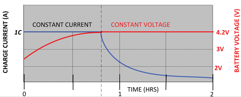
Charging Li+ batteries requires a two-step approach (see Figure 1).
Click image to enlarge
Figure 1. Constant-current/constant-voltage Li+ charge profile.
1. For a discharged battery, the first step requires the charger to be in constant-current mode. Maximum charging rates can be obtained in the battery manufacturer’s datasheets. The fast charge, or the 1C rate, is a charging current equal to the ampere-hour rating of the cell. As the battery is charging, the battery voltage reaches a specified set-point voltage, which is typically 4.2 V. At this point the cell capacity has reached only 65% to 70% of its maximum value.
2. As the second step of the charging process, place the charger in constant-voltage mode. In constant-voltage mode the charger will provide only enough current to maintain the battery voltage constant at this set-point voltage. As a result, the charging circuitry will continually reduce the charging current over time, resulting in a gradual decay of the charging current profile, as shown in Figure 1.
The circuit design
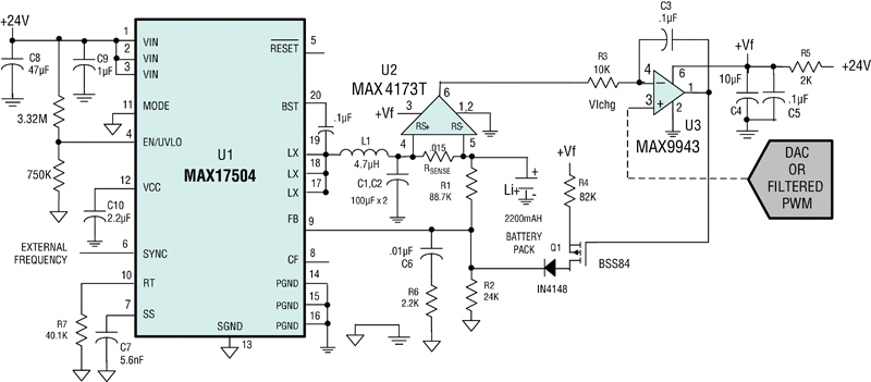
The heart of this circuit is the DC/DC switching converter U1 (see Figure 2). The MAX17504 has a wide input-voltage operating range from 4.5V to 60V and can be synchronized to an external clock frequency from 200kHz to 2.2MHz. This design idea has been tested to charge a single cell 4.2V to 2.2AH Li+ battery from a 24V input voltage.
Click image to enlarge
Figure 2. This battery charger provides constant-current/constant-voltage with frequency sync input.
When the battery load current is less than the preset charge current set point, VIchg, the charger is placed in constant-voltage mode as the output of integrator U3 will be driven to +Vf, thus biasing Q1 off. As such, the current through R4 will be close to zero and the charge voltage is set by (R2/R1 + 1) × .9V In constant-current mode the current control loop is formed by U2 and U3, where the charger current is set by the voltage on pin 3 of U3. U2 is a current-sense amp that measures the current across RS and provides the error voltage to the integrator formed by U3.
When the output voltage of U2 tries to exceed VICHG, the output of the integrator will then decrease its voltage and start to bias the Q1 sourcing current into the feedback node. This action lowers the converter’s output voltage, thereby reducing the current sourced to the battery.
This feedback loop will find the current-limit operating point based on the discharge state of the battery by the servo action of the integrator. The tested current accuracy (at 25°C) of this circuit at 24V was less than 1.6%. The output current is set to 1.5A by applying .450V to VIchg. The VIchg can originate from different sources such as a fixed voltage reference or PWM-filtered output from the MCU or DAC output. It is important to have a low-noise voltage source for VIchg.
This charger is unique because it can synchronize the switching frequency to an external clock and it has a wide input-voltage operating range. The battery charge current is set by Equation 1 when the circuit is in constant-current mode.
I charge = (VIchg/CSA gain)/RSENSE
Where CSA gain for the MAX4173 is 20 and RSENSE in this circuit is .015Ω.


