Analog and Power Management Solutions for Asset Tracking
The just-in-time philosophy for supply chains requires a constant stream of inbound shipments to fulfil customer orders and knowing their location is crucial
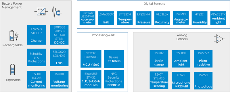
Figure 1: The major functional blocks of a battery-powered wireless connected asset tracker – key analog functions are highlighted in the shaded areas (source ST)
The internet of things has already transformed many business operations and consumer services, and the development of battery-powered wireless connected asset trackers continues the adoption of IoT technologies.
An asset tracker contains circuit functions to determine its position and communicate the location data with a unique identifier to a central tracking control system. Depending on the type of consignment they are tracking, a tracker may be placed outside a shipping container with materials on a pallet or on the vehicle making the delivery. Asset trackers are usually self-contained and operate from a battery source to provide maximum flexibility. Consequently, understanding the power consumption profile of the asset tracker is extremely important.
Another aspect of an asset tracker is that, since it can send location data, typically over a cellular wireless link, it could also send a small amount of additional information that might be useful. Some goods may stipulate strict temperature-controlled conditions, so sending the consignment's temperature provides an audit of the environmental conditions during its journey. A shipment prone to damage from mechanical shock would benefit from constantly monitoring acceleration forces and shocks. Sensors can provide information on various environmental, mechanical, and positional parameters. Figure 1 illustrates the major functional blocks of a wireless asset tracker.
Asset tracker design challenges
Reliability is a crucial design requirement for a self-contained asset tracker. Maintaining operation over weeks and months from a battery emphasises ultra-low power design. It is a delicate balancing act between minimising power consumption and higher power demands when sending regular tracking updates. Three design considerations stand out as requiring an in-depth review.
Efficient DC-DC conversion and regulation
Factors influencing the choice of battery include its capacity, the physical shape and dimensions, and the output voltage. It may be that the battery voltage does not cater to all required circuit voltages, so DC-DC conversion will be necessary to a step up or step down a supply rail. Also, the battery voltage will typically reduce slightly as its charge reduces, so tight voltage regulation should be employed to prevent erratic tracker behaviour.
Battery current and voltage monitoring
The battery's discharge state is an essential indicator of the tracker's operational status. Monitoring the terminal voltage and load current allows it to be sent together with location data and other vital sensor data to the host monitoring application. Since the monitoring circuits also depend on the battery for its supply, it is imperative that these functions also have low power consumption characteristics.
Fast and precision analog sensor design and signal processing
Discrete analog sensor circuits and digital sensor ICs should also have low power credentials. Op-amps are a popular method of architecting low power sensor elements and signal conditioning circuitry. Examples include the battery current and voltage measurement functions in addition to temperature, humidity, pressure, and strain parameters. Op-amps used in these circuits should also offer a quick and fast measurement capability. During active operation, the power consumption will increase, and the time duration for a sensor to register a precise value is key.
Selecting analog and power management components for a low power wireless tracker
Let's investigate some analog and power management components suitable for use in low power asset trackers, starting with power conversion and regulation.
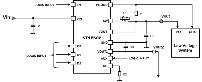
The ST1PS02 series is an example of a nano-amp quiescent step-down DC-DC converter from STMicroelectronics. This converter offers a no-load current consumption of just 500 nA, is 92 % efficient when supplying a 10 mA load, and can deliver up to 400 mA at full load. Designed specifically for compact wearable consumer electronics and portable industrial sensors, the ST1PS02 is constructed in a miniature TQFN12 plastic package measuring 2 mm x 1.7 mm x 0.55 mm. Figure 2 showcases the device used in an example use case. Only an inductor, some small decoupling capacitors and two resistors are necessary to enable all features of the DC-DC converter circuit.
Click image to enlarge
Figure 2 - An example application using the high efficiency ST1PS02 400 mA nano-quiescent synchronous step-down DC-DC converter with digitally selectable output voltage (source ST)
The ST1PS02 series has an input voltage range of 1.8 V to 5.5 V and can deliver a single selectable output voltage (device dependent) between 1.0 V to 3.3 V. The logic inputs D0, D1, D2 determine the precise output voltage setting which can be hardwired on the PCB. Alternatively, the output level can be controlled from the MCU to optimise the voltage level according to application requirements. An under-voltage lockout feature disables the output, should the input fall below 1.57 V. Output voltage regulation is maintained within +/- 1.5 % of nominal output.
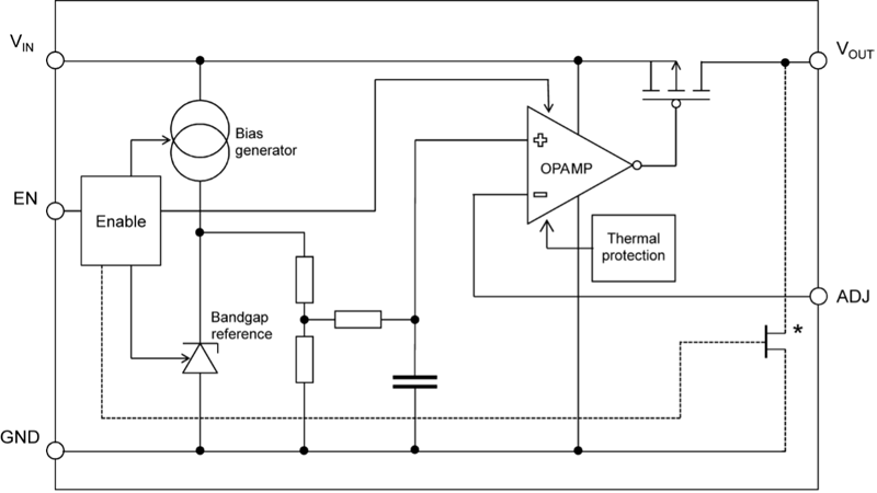
Another low power management IC suitable for asset tracker applications is the STLQ020 series. This 200 mA low-dropout voltage regulator can accommodate an input voltage between 2 V to 5.5 V and has a no-load consumption of 300 nA. The series is available with either a fixed output voltage, in the range of 0.8 V to 4.5 V, or with an adjustable output voltage. Figure 3 shows the internal architecture of the fixed output voltage variant of the STLQ020 series.
Click image to enlarge
Figure 3 - The internal architecture of the low power 200 mA ultra-low quiescent current LDO (source ST)
As previously mentioned, measuring the battery's voltage and the load current provides a reliable indication of the asset tracker's health status. Ultra-low-power op-amps offer a viable method of measuring low currents. Suitable devices include the TSU101 and the TSU111 from ST. The TSU101, for example, is a 580 nA per channel op-amp capable of rail-to-rail operation with a low supply voltage range from 1.5 V to 5.5 V. The gain-bandwidth product of 8 kHz makes them suitable for a range of battery-powered, portable sensor and signal conditioning applications.
Figure 4 shows an example current sensing application using a shunt resistor to measure the current. The input voltage offset through the divider requires a low bias current op-amp to prevent influencing the current measurement. The ST TSU111 op-amp, highlighted in Figure 4, offers high accuracy, typically 150 mV, 11.5 kHz gain-bandwidth, and a ten pA input bias current, and zero-drift technology providing temperature stability as well as high precision.

Click image to enlarge
Figure 4: A current measurement reference circuit using a TSU111 nano power high accuracy op-amp (source ST)
We can measure different input current ranges by tuning the resistances (Rsense = 100 mOhm) and Vref. The critical factor is the absolute minimum current capable of measurement. In the circuit, the impedance seen from the Rsense towards the op-amp is high, so the current drawn is negligible.
What is critical is the bias current from the op-amp, which flows through the 100 Ohm resistors. Even one mV over sense resistor, as illustrated in Figure 4, will generate an error and order of magnitude higher than the 150 mV offset voltage of the selected op amp.
Another sensing example is for the asset tracker to measure the ambient temperature. Figure 5 highlights a simple sensor example using an ST STLM20 precision analog ultra-low current temperature sensor with a ST TS883 rail-to-rail nanopower dual comparator.

Click image to enlarge
Figure 5: An example analog temperature sensor circuit incorporating the ST TS883 nanopower comparator (source ST) - (NOTE FIGURE NEEDS TS332 changing to TS883)
The two comparators of the TS883 are configured to monitor the ambient temperature within ±10 °C of a +25 °C centre temperature. Resistors R1, R2, R3 create a voltage divider to set the two comparator reference voltages. At 25 °C, the output voltage is 1.574 V, and the highest temperature limit of 35 °C, the output is 1.457 V, and at the lower threshold 15 °C, the output is 1.691 V. Further details on how to create a similar design and how the resistor values are calculated can be found in ST Application Note AN4071.
The TS883 is a rail-to-rail 0.9 V open drain dual comparator. Current consumption is typically 250 nA per comparator.


