Fuel saving automotive start/stop electronic systems
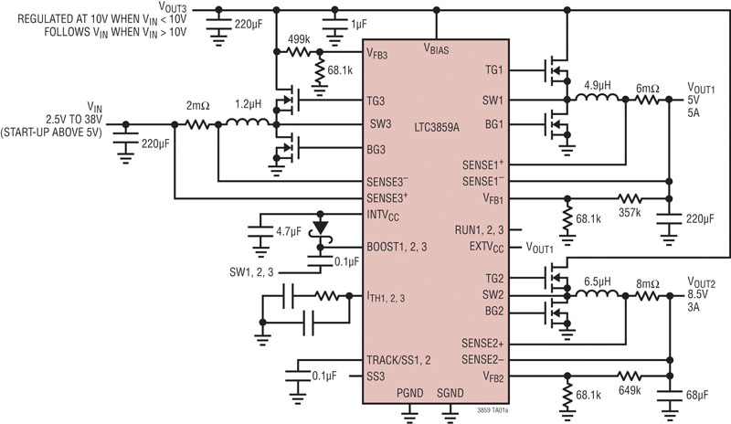
Figure 1: Typical LTC3859A Start/Stop Application Schematic
Many automotive manufactures have devised a clever way of saving fuel in automobiles by using a new concept called a "Start/Stop" system. This system automatically switches off the engine when the car is at a standstill and in neutral, then restarts it as soon as the driver presses the clutch pedal again. The principle of this is simple, if the engine is not running, it does not consume fuel. In a traffic jam or even in stop-and-go traffic, simply putting the car into neutral and taking the foot from the clutch will activate the function. A Start/Stop message on the info display will signal that the engine has been turned off. To start up the engine again, depress the clutch, put the car back into gear and the engine immediately springs back to life ready to drive on without delay. Driving comfort and safety are not affected by the Auto Start/Stop function. The function is not activated, for example, until the engine has reached an ideal running temperature. The same applies if the air conditioner has not yet brought the cabin to the desired temperature, if the battery is not adequately charged or if the driver moves the steering wheel. The Auto Start/Stop function is coordinated by a central control unit that monitors data from all relevant sensors, including the starter motor and the alternator. If necessary for comfort or safety, the control unit will automatically restart the engine. For example, if the vehicle begins to roll, the battery charge falls too low or condensation forms on the windscreen. Furthermore, most systems recognize the difference between a temporary stop and the end of the trip. It will not restart the engine if driver's seatbelt is undone, or if the door or trunk is open. If desired, the Auto Start /Stop function can be completely deactivated with the press of a button. However, when the engine restarts and there is an infotainment system on or any other electronic device requiring greater than 5V, there is a possibility that the 12-volt battery can dip to below 5 volts causing these systems to reset. Some infotainment systems operate from a 5V and 8.5V input voltage fed from a step-down converter operating from the car battery. When the input voltage dips to below 5V during an engine re-start (cold crank), these systems will reset when the DC/DC converter only has the capability to stepping-down the input voltage. Obviously, it is not acceptable to be watching a video or listening to a CD and have them automatically reset every time the car restarts. A New Solution Linear Technology has a triple output DC/DC controller, the LTC3859A that combines a synchronous boost controller and two synchronous step-down controllers in a single package. The synchronous boost converter output feeds the step-down converters to maintain a high enough voltage to prevent electronic systems requiring greater than 4V to reset during an engine restart. In addition, when the input voltage from the car battery to the boost converter is higher than its programmed output voltage, it runs at 100% duty cycle and simply passes the input voltage directly to the step-down converters minimizing power loss. Figure 1 shows a LTC3859A schematic with the synchronous boost converter supplying 10 volts to the synchronous step-down converters when the battery voltage drops below 10 volts. In addition to powering the two step-down converters, which produce 5V/5A and 8.5V/3A in this example, the boost converter can be used as a third output that can provide an additional 2A output. The LTC3859A is low quiescent current, current mode control, triple output synchronous DC/DC controller that operates with all N-channel MOSFETs from input voltages ranging from 4.5V to 38V during start-up and can operate down to 2.5V after start-up. The two buck controllers, channels 1 and 2, operate 180 degrees out of phase and can produce output voltages from 0.8V to 24V that are ideal for navigation, Infotainment systems, processors and memory. The boost controller, channel 3 operates in phase with channel 1 and can produce output voltages up to 60V. The powerful 1.1? onboard gate drivers for each channel minimize MOSFET switching losses. The operating frequency can be programmed from 50kHz to 900kHz or can be synchronized to an external clock with internal phase-locked-loop (PLL) over a 75kHz to 850kHz range. The LTC3859A differs from the LTC3859 by having an internal clamp on the INTVCC pin. This clamp is a failsafe approach that prevents excessive voltage on the INTVCC pin if the user inadvertently uses a leaky schottky bootstrap diode. Additional features include an onboard LDO for IC power and gate drive, programmable soft start, a power good signal and external VCC control. The VREF accuracy is ±1% over an operating temperature range of -40°C to 85°C and the LTC3859A is available in the 38-lead SSOP or a 38-lead 5mm x 7mm QFN packages.

Extending Battery Run Times Any battery powered system that requires an "Always-On" power bus while the rest of the system is turned off must conserve battery energy. The need for low quiescent current to conserve battery energy is especially important in automotive applications that can have several electrical circuits such telematics, CD/DVD players, remote keyless entry and multiple always-on bus lines. The LTC3859A draws a mere 75μA when in sleep mode with the boost converter and one of the buck converters on. With all three channels on and in sleep mode the LTC3859A draws only 100μA which significantly extends battery run times when in idle mode. This is done by configuring the part to enter high efficiency Burst Mode® operation, were the LTC3859A delivers short bursts of current to the output capacitor followed by a sleep period where the output power is delivered to the load by the output capacitor only. Figure 2 shows the conceptual timing diagram of how this works. The Burst Mode output ripple is load independent, only the length of the sleep intervals will change. In sleep mode, much of the internal circuitry is turned off except for the critical circuitry needed to respond quickly, further reducing its quiescent current. When the output voltage drops enough, the sleep signal goes low and the controller resumes normal Burst Mode operation by turning on the top external MOSFET. Alternatively, there are instances when the user will want to operate in forced continuous or constant frequency pulse skipping mode at light load currents. Both of these modes are easily configurable, will have a higher quiescent current and a lower peak to peak output ripple.
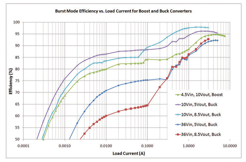
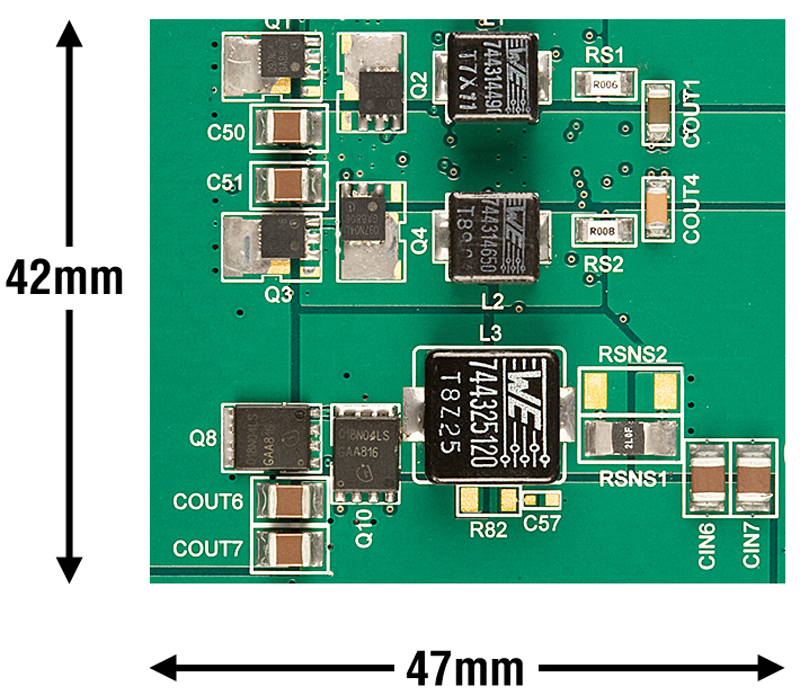
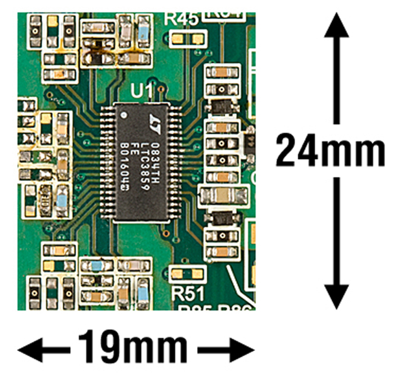
Load-Dump/Efficiency/Solution Size Load dump is a term that refers to the inductive kick that happens after the starter motor is turned off. This surge voltage is normally clamped to 36 volts maximum for a 12 volt lead acid automotive type battery system. This surge requires the controller, MOSFETs and associated components being capable of operating at the clamped voltage. These higher voltage devices (such as 40V MOSFETs) can degrade efficiency and care must be taken to minimize this effect. Based on the circuit in Figure 1, the efficiency is above 92% for each rail as shown in Figure 3. For clarity the efficiency of each buck and boost section is show separately. In addition, the layout and circuit size for this circuit is shown in Figure 4 with the tallest part being 4.8mm high.
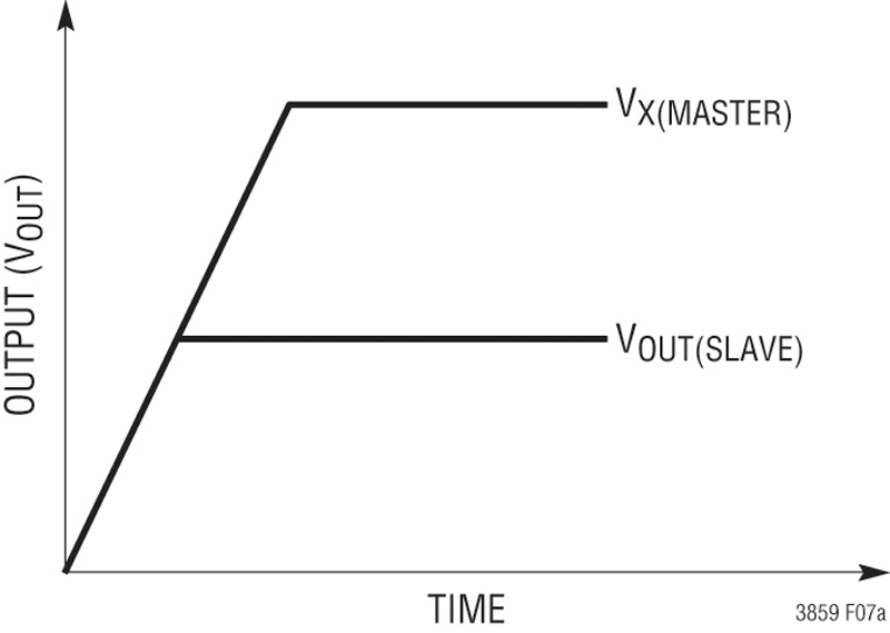
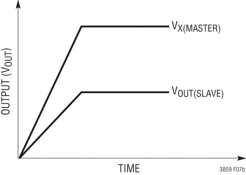
Soft Start or Tracking The TRACK/SS1 and TRACK/SS2 pins of the two buck controllers can be used for adjusting the soft start turn-on time or to track two (or more) supplies with Coincident or Ratiometric tracking during start up. These associated curves are shown in Figure 5 and is accomplished by putting a resistor divider from the master supply, to the TRACK/SS pin of the slave supply.
At higher temperatures, or in cases where the internal power dissipation causes excessive self heating on chip, the over temperature shutdown circuitry will shut down the LTC3859A. When the junction temperature exceeds approximately 170°C, the over temperature circuitry disables the on-board bias LDO, causing the bias supply to drop to zero volts and effective shutting down the entire LTC3859A in an orderly manner. Once the junction temperature drops back to approximately 155°C, the LDO turns back on. Conclusion The LTC3859A provides a solution by boosting the battery voltage to a safe operating level with is onboard synchronous boost controller. Combined with two synchronous step-down controllers, ideal for powering many automotive electronic devices, the LTC3859A maintains regulation for all output voltages during an engine restart. www.linear.com


.jpeg)
 Single.jpeg)
