Benefits of Digital Switching in Programmable AC Power Sources
Digital power conversion design techniques can reduce the size and weight of programmable AC power design while unlocking enhanced functionality.
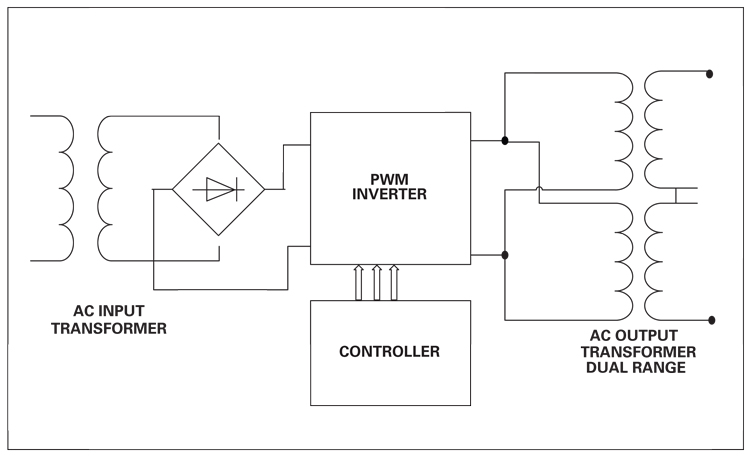
Figure 1. Conventional AC power source topology
Programmable AC power sources have been widely used to implement and support numerous product test procedures over the years. They provide the test engineer with the ability to fully control voltage, frequency, and current to the unit under test (UUT). Products like these are used to simulate various power conditions and anomalies that are likely to occur in actual use of AC and DC powered products. They also are essential for providing the requisite 400-Hz or 800-Hz frequency AC power for military and avionics power subsystems.
These types of instruments provide the following features and benefits to the design and/or test engineer:
· Safety isolation between the AC grid input and UUT output;
· Conversion of any grid voltage and frequency found around the world to a specific desired output frequency to the UUT;
· Precise control over output voltage, including line and load regulation;
· Stable and controlled output power, immune to any AC line input fluctuations or momentary voltage drops; and
· Phase conversion from single-phase to three-phase, single-phase to split-phase, or three-phase to single-phase.
Conventional AC source topologies and design
The vast majority of available AC power source designs are based on pulse-width-modulated control circuits and the use of low-frequency transformers to provide isolation between input and output of the AC power source.
These PWM designs generally use analog control circuits to provide output regulation, current-limit functions, and frequency-conversion functions. While this is a proven design it does have some drawbacks:
· The use of line frequency AC input transformers to provide galvanic isolation adds significant size and weight to the product, especially as power levels increase.
· The use of output transformers to provide galvanic isolation causes similar increases in size and weight and prevents the capability to generate DC output capability. Furthermore, such output transformers must support the wide frequency range complicating their design and increasing cost.
· Analog control loops are affected by discrete-component variations and temperature drift. This negatively affects accuracy and stability, and it requires adjustment pots for calibration.
A simplified block diagram of this topology is shown in Figure 1. It shows a single-phase input, single-phase output source, but a three-phase version is similar in design.
Digital power conversion
The higher PWM switching speeds required to support the wide output frequency range of an AC source, often higher than 30 kHz, have made it difficult to use DSPs to provide all control functions. With the advent of recent advances in performance and cost of DSP technology, a full digital implementation of an AC power source design supporting these switching frequencies now is feasible.
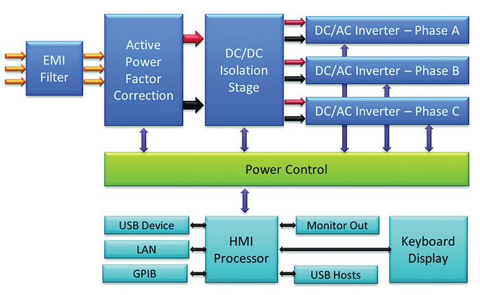
A good example of this is the Pacific Power AFX Series programmable AC and DC Power source. This product uses a three-stage, all-digital power converter design. This design eliminates both AC input and output transformers and results in a power density five times higher than similar contemporary products and a four-fold reduction in weight. Figure 2 shows the size of a 15-kVA programmable source using all digital design vs. a conventional analog 15-kVA power source.
All-digital-control advantages
Using all-digital control of critical power conversion stages eliminates a lot of the tolerances and variations associated with analog components and control circuits. Furthermore, the capability to monitor and control switching events in real time, on a cycle-by-cycle basis at the PWM switching frequency, yields greater protection against load- or line-induced anomalies that may occur. This level of protection is no longer subject to analog filtering and averaging, which introduces delays in conventional power source designs.
 vs. a conventional 15kVA power source (right).png)
Click image to enlarge
Figure 2. 15kVA digital design AC source using (left) vs. a conventional 15kVA power source (right)
These advances allow the following topology changes:
· Replacing an AC input transformer used for isolation with an active power-factor-corrected AC/DC conversion stage followed by a very-high-frequency DC/DC conversion stage with galvanic isolation dramatically reduces the size and weight of the input stage components.
· Replacing any output transformers or series/parallel output inverter stages with a single high-output-voltage inverter supports both low-voltage/high-current and high-voltage/lower-current requirements.
This digital control-based topology is shown in Figure 3.
Click image to enlarge
Figure 3. Digital AC power source topology
The use of all-digital controls yields a number of advantages:
· Lower weight and smaller size due to the elimination of input and output transformers,
· Higher power density and lower losses due to increased efficiency and high switching frequency for the reduction of output filter inductor size,
· Reduced output switching noise as a result of higher PWM switching speeds and improved digital filtering,
· A wider AC voltage input range with active power factor correction, and
· A constant power output voltage range for a wider operating area while eliminating the need for dual output ranges and associated range switching.
New user functions made possible
Providing greater control over each internal switching cycle allows unique new user functions aimed at providing greater protection of the UUT. It also minimizes possible damage to the power source itself, resulting from user errors in connections or possible prototype UUT-induced damage. Here are two examples and uses of such functions:
True power and/or apparent power limit functions
The capability to set a programmable current limit and a power limit is important for many UUTs that exhibit constant-power input behavior. A UUT that can operate from a wide AC input range, like 85 VAC through 265 VAC, cannot be protected by only a current-limit function. The same current that protects at 115-V input cannot protect the UUT if the input voltage is changed to 230 V. Only a true power-limit function will do this.
Peak current limit function
This feature allows the user to set a specific peak current limit for a UUT. The AFX power source will monitor actual peak current demanded by the UUT and clamp the peak current as soon as it exceeds the set limit value. This happens at the fundamental output frequency or for each period of the output voltage. It provides a level of protection that cannot be obtained using rms or average current limit protection functions alone.
Summary
In conclusion, modern advances in DSP throughput and cost have enabled higher switching frequency power-conversion stages, such as those required for instrument-grade programmable power sources to use an all-digital implementation. This design not only improves performance due to the deterministic nature of digital control, it also enables higher levels of protection for both UUTs and the power source itself to be realized.
Pacific Power Source, Inc.


.jpg)
