Selecting the Right Battery Monitoring IC Features for Reliable Isolated BMS Communications
It is no surprise that analysts have predicted continued growth in the usage of Lithium Ion (Li-Ion) battery cells for energy storage and automotive applications through 2025 with growth rates of up to 30 percent forecasted to support China’s transportation market alone. In various forms of mobility applications, Battery Management Systems (BMS) are used to connect to high-energy battery packs and manage the charging, discharging of the pack. The BMS also monitors vital operational factors such as temperature, state of the charge along with the battery pack’s overall health. If needed, the BMS can connect and disconnect the battery from the load or charging source for added protection.
This article highlights the main battery monitoring IC features OEMs need to consider in a BMS for energy storage design. Background information is provided on battery cell chemistries and their relationship to the requirements for communications in a high-voltage BMS. The article will also provide an energy storage application example that presents the decision-making process for selecting the optimum transformer that meets design specifications.
Battery Cell Chemistries
A summary of the most popular chemistries by energy density, cell voltage and charge rate for 48V and higher voltage battery packs is provided in Table 1. These higher voltage packs are necessary to satisfy the power density required to drive new electronics and motor designs. Understanding these needs, battery cell suppliers have developed a range ofdifferent chemistries designed to deliver the increased power energy over longer periods of time needed for full electric battery power.

Click image to enlarge
Table 1: Summary of Most Common Li-Ion Chemistries for Battery Applications
However, there are several factors to consider when choosing the chemistry for a battery powered application including energy density, resistance and operating temperature.
- Lithium Nickel Manganese Cobalt (NMC) with Graphite has the highest energy density among the commonly-used chemistries. This density is advantageous for heavy loads used in consumer energy storage or for plug-in electric vehicles. The disadvantage of NMC is it creates a higher risk of lithium plating on the anodes. This condition can reduce battery life and can lead to thermal runaway (fire or explosion). These harmful conditions become worse with today’s faster charging connectors.
- Lithium Titanate (LTO) has a lower energy density than NMC and does not suffer from the problem of cracking graphite, thereby, improving estimated battery life. The lower internal resistance of LTO facilitates faster charging rates making this battery chemistry beneficial for plug-in electric vehicles. The downside is it requires heavier battery packs as more cells are needed to provide the necessary energy in kilowatt hours (KWH), which also increases costs. In general, Lithium chemistries have very narrow operating temperature ranges, typically from 20C to 40C. Applications that call for operating outside these temperatures jeopardize the cell’s capacity and lifespan specifications. Elevated temperatures can also cause furtherdegradation and a thermal runaway condition. A paper by Nasa[1], which studied the protection within 18650 cells found that the interrupt devices in all the cells connected in series and parallel were not aseffective as single cells in preventing thermal runaway during faultconditions. This study illustrates the strong need for a Battery Management System when multiple cells are interconnected.
BMS IC and Transformer Functionality

Click image to enlarge
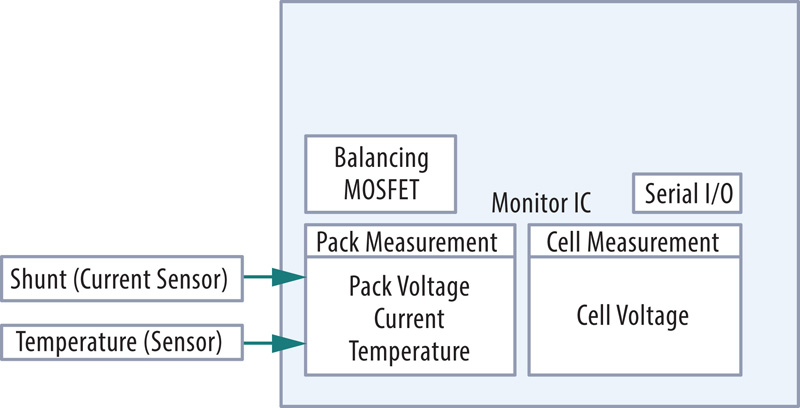
Figure 1:This block diagram of a typical Battery Management System shows the functions for monitoring essential battery pack health
A typical IC used as a monitoring device in a BMS functions to measure cell voltage, pack temperature and to perform cell balancing shown in Figure 1. High-voltage battery pack IC designs do not require a current sense function. That is because these packs need only one current sensing chip and several hundred monitoring ICs to monitor the individual cells in the pack. A simple way to determine the number of monitoring ICs required is if each monitoring IC can check 10 cells, then at least 130 monitoring ICs will be needed. Another consideration in high-voltage battery packs is that the BMS IC module or board needs to be located on top of the shunt resistor, which may pose a mechanical design challenge.
Designing for Isolated Communications
Isolated communications in a BMS is typically handled with two ports that allow battery monitoring modules to be daisy-chained throughout the battery pack. The source and sink currents of the serial port drivers are balanced enabling the IC to drive a transformer without saturating it. A transformer with a rated working voltage of several hundred volts is required to provide the necessary protection of the communications line from any hazardous voltage coming from the battery pack. Furthermore, the drivers on the IC encode a four-line serial peripheral protocol into the differential signal to enable isolated communication from board to board.
The Serial Peripheral Interface (SPI) is an interface bus commonly used to send data where one device or “master” transmits a clock pulse and control bit to a series of slaves. On each clock pulse, the slave either reads a command from the master or if the control bit is inverse, transmits its data on the data line. This enables a central battery controller IC (master) to interrogate each monitoring IC (slave) in turn and, hence, retrieve necessary voltage and temperature information from the whole pack. In addition, the transformer and integrated common mode choke are employed to filter out common mode noise from the daisy-chained network.
Click image to enlarge
Figure 2: A BMS transformer with a centre tap capacitor and resistor can improve Common Mode Noise Rejection
Although BMS ICs have balanced currents on their I/O pins, most manufacturers recommend a centre-tapped transformer shown in Figure 2. These have been found to improve CMNR if a filter capacitor and termination resistor is used.
BMS Transformer Safety Testing
It is important in high voltage energy applications to test the electric strength by determiningthe voltage at which a dielectric material such as an insulator in a transformer will withstand without breaking down. A “Hi-POT” test is usually the way this is verified. The test is conducted by applying high voltage between the primary circuits and the protective transformer.
Per Table 2N of IEC6090, the minimum creepage distance for material group I, pollution Degree 2 of functional insulation for a working voltage of 1600V is 8.00mm. The replacement test for IEC60950 (IEC62368-1), which becomes mandatory June 2019 for audio/video, information technology and communication equipment will recognize FIW in the future. The use of FIW in certain transformer may qualify the device as having reinforced insulation with a lower working voltage (depending on the standard) of approximately 800V. This would allow the device to meet UL approval requirements and enable its use in additional applications such as consumer energy storage, which mandate reinforced insulation.
Recommended Electrical Characteristics
The recommended primary inductance values provided by various IC manufacturers will depend on the voltage of the communication signals, the pulse widths and the frequency. For example, Bourns designed its Model SM91051AL transformer with a primary inductance span between 150uH and 450uH over an operating temperature range of -40C to +125C. Since inductance is directly proportional to permeability of the core, the permeability of a transformer’s ferrite core is temperature-dependent, and tends to increase with temperature. Therefore, the primary inductance of the Bourns transformer cited will increase to approximately 450uH at the upper end of the temperature range. This demonstrates why there can be large variations in inductance values that suppliers specify on their datasheets.
Evaluating the noise immunity of the BMS IC and transformer can be done with a bulk current injection (BCI) test. The BCI test injects current into the twisted-pair lines at set levels over a frequency range of 1MHz to 400MHz with the bit error rate being measured. A 40mA BCI test level is sufficient for most industrial applications, where a higher 200mA test level typically needed for automotive BMS designs.
![]()
Click image to enlarge
Figure 3: Bourns Model SM91051AL and SM91051AL transformers have been evaluated by BMS IC manufacturers for automotive applications and have successfully passed requirements for BCI
Ensuring Reliable Isolated BMS Communications
Along with increased demand and subsequent growth for Li-Ion battery power, Battery Management Systems with reliable isolated communications are expected to be an important part of the safety and security of the energy system. An effective BMS is an essential design element that will help increase the lifespan of Li-Ion cells and contribute to enhanced safe operation for end users.
For high-voltage BMS designs, it is essential to specify transformers with the elevated working voltages of 1600V and 1000V as well as those with ideal inductance values of 150 μH and 450 μH over an operating temperature range of-40 ˚C to + 125 ˚C to match higher voltage BMS requirements. In addition to enhance the safety features of the BMS, it is important to select a transformer designed with windings that use fully-insulated wire passing the dielectric strength (Hi-POT) test. Doing so further increases the electrical insulation protection from overvoltage transients making them ideal solutions for isolated BMS communications in automotive, industrial and consumer energy storage applications.