Collaborating for Success in Custom Power Magnetics Designs
Reduce risk and costs for power magnetics designs with proactive, holistic design strategies
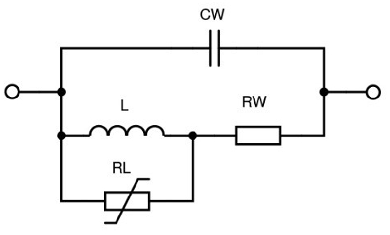
Figure 1. Simplistic inductor equivalent circuit
Despite its long history, the theory of magnetics component design still eludes many engineers, and with some justification; a good description of the effect of a magnetic field is the ‘relativistic correction to the force between charged particles when in motion.’ Many understand the behaviour of magnetics components at a basic level – but a deeper challenge arises when the influence of real core materials comes into play with second-order electrical effects, further complicated when the component must be designed for its smallest size, with minimum losses at lowest cost.
Choices may seem obvious: if there is space, a larger part might have more copper and lower DC losses, but material cost would be higher and AC losses could actually be worse. All things being equal, larger ferrite cores have high-frequency losses which scale with core volume. It’s an example of how magnetics design needs to account for multiple interacting characteristics. In these applications, true subject matter expertise is extremely beneficial and enables detailed discussions to clarify parameters such as DC resistance, leakage inductance, self-resonance, winding capacitances, isolation/safety ratings and much more. The resulting insight makes clear design trade-offs and their likely effects on long-term, mission-critical performance.
Customised components are typically a better fit; however, designers must understand the complexities of magnetics including a range of parameters that impact performance, cost, and potential trade-offs required throughout the device’s design.
Magnetics have many parameters
Depending on the application, factors such as inductance L, current rating, winding resistance RW, non-linear core losses RL, winding capacitance CW, leakage field, self-resonance, saturation characteristics and more might be crucial parameters (Figure 1). This would be for an inductor, but transformers require still more considerations including winding ratios, isolation/safety ratings, mutual inductance, inter-winding capacitance, and more. Many parameters vary with temperature and drive level and are in turn interdependent. All types have a wide range of possible mechanical formats. The permutations multiply dramatically – and while distributors of standard parts may stock popular variants, it is unlikely that any single option will fit all requirements exactly. Custom parts add value and should be considered.
Inductor specifications
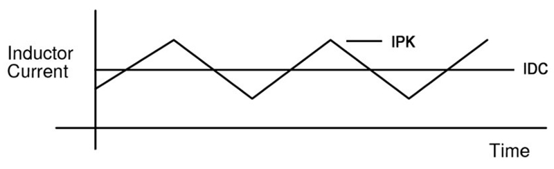
Details about current flows and available space are insufficient specifications to provide to a custom magnetics supplier. For example, the discussion should include a specification for inductance tolerance. Calculations will yield a required inductance; a wider acceptable range makes for easier manufacturing and lower cost, especially at high inductance values. The current waveform should also be specified; DC only produces ohmic losses, but any AC component generates core losses that are of strong frequency and level dependent. Core saturation must be avoided but is an instantaneous effect, so peak value of any AC current should also be specified (Figure 2).
Click image to enlarge
Figure 2. Typical buck converter inductor current with a high AC component
Even saturation has its characteristics. For instance, ferrite cores lose inductance suddenly at a threshold current but other types, such as iron powder, drop their value more gradually. If transient overloads are possible, this might be more desirable although powder has higher AC losses than ferrite, a situation in which a supplier can advise ideal trade-offs.
Operating temperature is a major consideration. For standard parts, maximum surface temperature rise is normally rated but the point of measurement varies. The limit can be reached for different reasons as well, either because of ohmic losses, core losses with AC bias, or a combination of both. Specifying the actual current waveform and a maximum ambient temperature allows the supplier’s design team to select wire gauges and core materials. These can be selected to ensure acceptable surface temperature rise for the materials used in a given ambient.
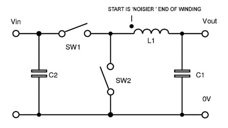
Leakage field around an inductor may also represent a system issue, producing EMI and coupling to other components. While it would be difficult to specify an acceptable level, it is useful to tell a supplier that it might pose a problem. This would steer the design towards a solution that offers an element of self-shielding. Drum cores are especially bad for external field but are very low cost while enclosed structures, such as pot-cores or some E-cores, are much better yet more expensive. The required inductance will affect the decision – if it is high, drum cores with their inherent large gap would require many turns of thin wire with high consequent resistance and losses (Figure 3).
Click image to enlarge
Figure 3. Noisy end of an inductor as innermost layer for shielding effect
Transformer specifications
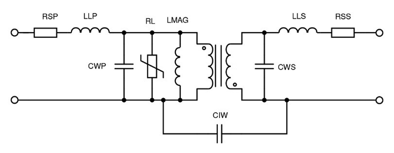
Power transformers are even less standard and have more parameters to consider (Figure 4).
Parasitic transformer characteristics, such as leakage inductance LLP and LLS, can affect circuit performance dramatically, sometimes for the better. Some resonant converter topologies require a minimum value and a simplistic design would integrate this as a separate, discrete component. It could be built-in to the transformer; however, this requires judicious placement of windings and core gaps. Expertise is critical here, ensuring design viability while maintaining other specifications and isolation ratings that save the cost and space of a discrete external component.
Click image to enlarge
Figure 4. Transformer equivalent circuit
Designing for an exact isolation rating is a skill that a custom magnetic suppler will often possess, with knowledge of the creepage and clearance requirements for various safety standards. Materials used should be in an approved insulation system which makes agency acceptance much easier. Designers can save significant resources by tapping into a supplier-recommended combination of wire, tape, plastics, varnish, etc., that are proven to be compatible.
Custom magnetics suppliers will sometimes support power converter reference designs – an excellent way to achieve the promised performance from a specific PWM IC, for example, with low-cost electromagnetics.
Tap into specialised design skills and experience to eliminate risk
Inductors and transformers existed long before almost any other components in electrical and electronic circuits, and they haven’t changed in their principle of operation since their invention in the 19th century. They are invariably a coil of wire around a core material and use the same basic design equations with arcane units named after the great scientists of the day –Henry, Gauss, Oersted and Tesla (although ironically it was Faraday who first discovered the underlying principles of induction). While many other electronic components have changed beyond recognition, development of magnetics has been stubbornly slow with only incremental improvements to winding methods and core materials for lower losses and smaller size.
Where it may appear that designs can choose between E-cores, toroids, drum cores and more with through-hole and surface-mounts, a specialist supplier’s design team has already faced these choices – and can advise when there are electrical trade-offs between each of these choices. Given these complexities, the perfect power magnetics component for your robust or critical application is unlikely to be found in a catalogue listing. Collaboration is at the core of developing an optimum solution.