Convert a buck regulator into a high-current LED driver
Coercing a voltage regulator to provide a constant current can extend your drive capability while maintaining low BOM cost.
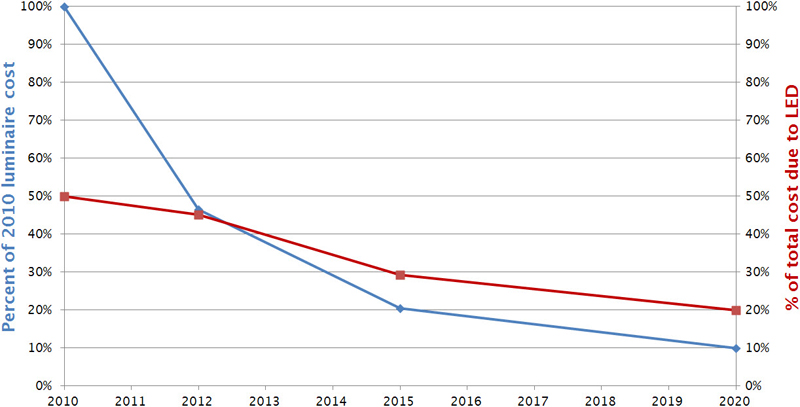
Figure 1: Projected relative cost of LED Luminaire and percentage due to the cost of LEDs (Source: DOE SSL 2011 Manufacturing Roadmap)
LEDs promise to change the world, and few doubt that they will. However, a key limiter to more rapid adoption is the cost of the LEDs themselves. The cost breakdown of LED luminaires varies, but it is safe to put the expense of the LEDs at around 25-40% of the total luminaire cost (reference 1). Projections suggest that LEDs will continue to represent a significant fraction of the total luminaire cost for many years (figure 1). One way to reduce the total luminaire cost is to drive an LED at its highest possible current. If driven properly, these LEDs produce more lumens per unit cost. Doing so, however, requires higher current drivers. While there are many drivers available to operate LEDs at low currents (< 500 mA), there are fewer options at higher currents (700 mA to 4.0 A). This is all the more surprising given that the semiconductor world is rich with DC-DC converters that can source as much as 4.0 A. The problem is that these DC-DC converters control voltages, not LED currents. Fortunately, there are some easy methods to take a readily available DC-DC buck regulator and convert it into an LED driver.
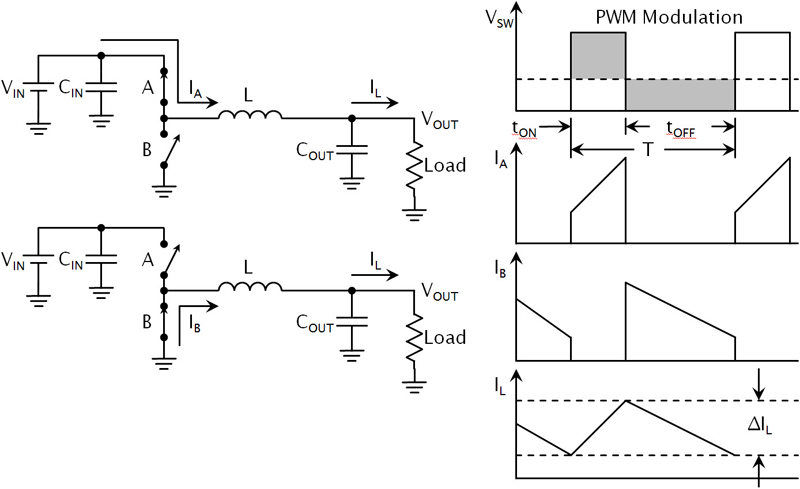
A buck regulator simply chops up an input voltage, passes it through an LC filter, and gives a stable output (figure 2). To do this, the buck employs two active elements and two passive elements. The active elements are a switch, A, from the input to the inductor and a switch, B, or diode from ground to the inductor. The passive elements are the inductor, L, and the output capacitor, COUT. These form an L-C filter, which reduces the ripple the active elements create. If the switches are internal to the IC it's a regulator, otherwise it's a controller. If both switches are power transistors—MOSFETs or BJTs—then it's synchronous, otherwise it's called asynchronous. This gives several categories of buck circuits and each has its own merits and drawbacks. A discussion of which type to use, and all the tradeoffs, would be extensive. However, in a very general sense, the selection that often times gives an optimal efficiency, parts count, BOM cost, and board area is a synchronous buck regulator.
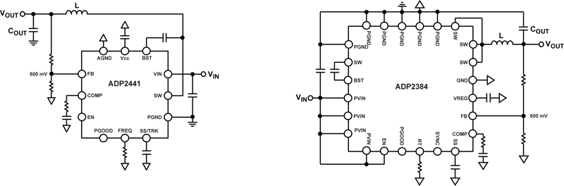
However, synchronous buck regulators for driving high current LEDs—up to 4 A—are few and expensive. An alternative is to take a standard synchronous buck regulator and modify it to regulate LED current. Here, we'll use as examples two general-purpose synchronous buck regulators from Analog Devices: the ADP2441 and the ADP2384. The ADP2441 is a high efficiency, 36-V input synchronous buck regulator, capable of producing an output current of up to 1.2 A. The ADP2384 is another high-efficiency synchronous buck regulator, but with an output current of up to 4.0 A, and an input voltage up to 20 V (figure 3).
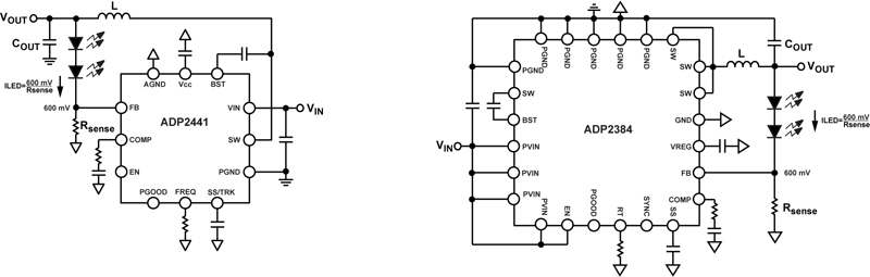
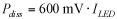
For both the ADP2441 and the ADP2384, the output voltage is resistor divided down to the FB pin, compared against an internal 600-mV reference, and used to generate the proper duty cycle to the switches. In steady state, this FB pin regulates to exactly 600 mV. So instead of a resistor divider, it is easy to put the LEDs there, with a resistor, RSENSE, in series to set the current (figure 4).
Using a precision resistor from FB to GND sets the LED current to
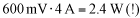
This works nicely, but it produces a lot of power dissipation:
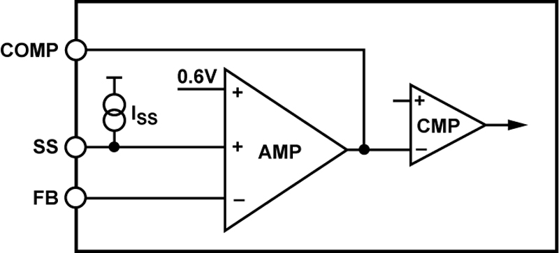
For low LED currents, the sense-resistor dissipation is not a big issue. But at high LED currents the impact to efficiency adds significantly to the heat that the luminaire must dissipate:
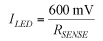
Fortunately, there are two methods to reduce the FB reference voltage for most buck regulators: use the SS (soft-start) or TRK (tracking) pin or offset the Rsense voltage. Many general-purpose buck ICs include an SS or TRK pin. The SS pin provides a controlled inductor current at startup. The TRK pin forces the buck regulator to follow an independent voltage. Often times the pins are combined into one SS/TRK pin. In most cases, the error amplifier will use the minimum of the SS, TRK, and FB_ref voltages to change the regulation point (figure 5)
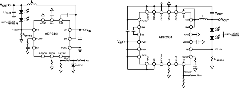
For the current purposes, we want to just set the SS/TRK pin to a fixed voltage and use it as our new FB reference. A resistor divider from a constant voltage to this pin works nicely. Many buck regulator ICs include a controlled low-voltage output, like the VREG pin on the ADP2384 or the VCC pin of the ADP2441. For greater accuracy, use a simple two-terminal precision reference such as the ADR5040, for example. Either way, a resistor divider from the supply to the SS/TRK pin forms the new reference (figure 6). Setting the resistor divider to give a SS/TRK voltage around 100 to 200 mV generally offers the best compromise between power dissipation and LED-current accuracy. Another benefit to setting your own feedback reference voltage is that this method can easily accommodate any sense resistor value in the standard-value series. This eliminates the expense and inaccuracy of paralleling multiple RSENSE resistors to set the LED current.
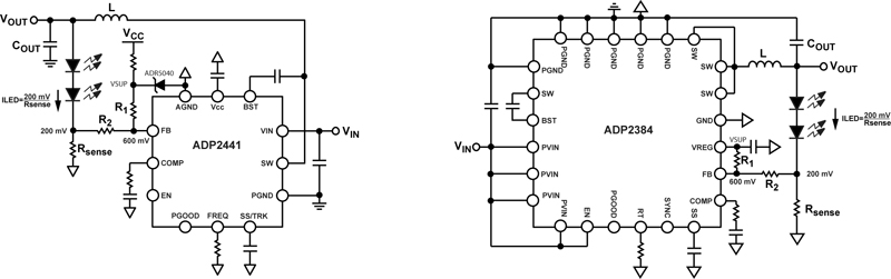
Using an SS or TRK pin accommodates many, but not all buck regulators. Some ICs do not have SS or TRK pins. Additionally, in some buck ICs, the SS pin changes the peak inductor current, not the FB reference so carefully check your buck-regulator's datasheet. If either of these situations is the case, you can use a different method: offset the RSENSE voltage. A resistor divider tied to an accurate rail between FB and RSENSE provides a fairly constant offset voltage between RSENSE and the FB pin (figure 7).
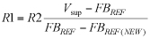
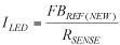
To implement the RSENSE voltage offset, calculate the necessary values for the resistor divider:
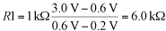
So to get an effective feedback reference, FBREF(NEW), of, say, 200 mV with R2 = 1 k? and VSUP = 3.0 V,
With this arrangement, the LED current is equal to:
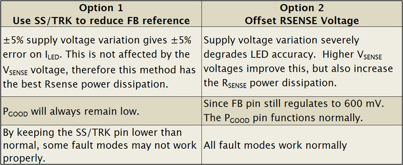
Using this method does not require a SS or TRK pin. Additionally, the FB pin will still regulate to 600 mV, but the voltage at RSENSE regulates to the FBREF(NEW) voltage. This means that other functions of the chip, such as soft start, tracking, and power-good indication will still function normally. The downside is that the accuracy of the supply can strongly influence the offset between RSENSE and FB. A precision reference like the ADR5040 has little problem. But if the supply in the above example had a �5% accuracy, it would create a �11% variation in the LED current. A comparison appears in table 1. These tips should be taken as general guidelines for implementing comprehensive LED features into a standard buck regulator. Because these features might be different from the intended application for the buck IC, however, it is always best to contact the semiconductor manufacturer to ensure that the IC can be used as described here. Analog Devices References: 1. SSL 2011 manufacturing roadmap, US Department of Energy, www.ssl.energy.gov 2. Marasco, Ken, How to apply DC-to-DC step-down (Buck) regulators successfully, Analog Dialogue, June 2011


