Satellite operators are offering increasingly sophisticated on-board processing capabilities with demanding, low-voltage, high-current, power requirements
Figure 1: FPATM vs. traditional, intermediate architecture
Smaller satellites harvest less energy and with operators increasingly using faster and more on-board processing, as much of the possible power budget should be available for the payload. Traditional power-distribution architectures comprising an isolated DC-DC to step-down the external bus input, followed by localised POLs, are becoming too inefficient because of large I2R drops. To deliver the next generation of space missions, improvements are needed in conversion loss, power density, physical size and a transient response compatible with the switching speeds of the latest ultra-deep-submicron devices.
Vicor’s Factorised Power Architecture (FPA) uses a modular approach to minimise I2R distribution losses, maximise efficiency and improve transient response. The FPAcomprises two stages: voltage regulation followed by transformation. First, a buck-boost topology is used to generate a 48 V intermediate rail from an external source, which is significantly higher than the lower legacy buses typically input to POLs. For example, a 48 V output bus requires four times less current than a 12V intermediate bus for the same power (P=VI) and PDN losses are the square of the current (P=I2R), which reduces by sixteen. Placing a regulator first to produce 48 V achieves the highest efficiency.

Click image to enlarge
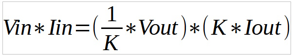
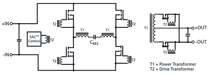
Figure 2: The full-bridge, SACTM series-resonant topology
The second stage of the FPA uses a transformer to convert the 48 V intermediate rail to the desired load voltage. The output is a fixed fraction of the input (K factor) defined by the turns ratio. Stepping-down the voltage increases the current by the same amount, e.g. a 1 A input current would be multiplied to an output of 48 A:
A Pre-Regulation Module (PRM) and a Voltage-Transformation Module (VTM) current multiplier combine to realise the FPA, with each device fulfilling its role to enable complete DC-DC conversion. The PRMgenerates a regulated ‘factorized bus’ from an unregulated input followed by the VTM, which transforms (steps-down) the 48 V to the desired load voltage.
The VTM's high bandwidth avoids the need for large point-of-load capacitance. Even without any external output capacitors, the output of a VTM exhibits a limited voltage perturbation in response to a sudden power surge. A minimal amount of external bypass capacitance (in the form of low ESR/ESL ceramic capacitors) is sufficient to eliminate any transient voltage overshoot. Without imposing the bandwidth limitations of an internal control loop struggling to maintain regulation, the VTM offers a unique capacitance-multiplication feature. For example, the effective, shunt, output capacitance is 2304 times the input capacitance when a K factor of 1/48 is used, i.e. Csec = Cpri * K2. This means that significantly less decoupling is needed downstream of the VTM and only a small amount of capacitance at its input offers the same energy storage as the bulky tantalums typically added to the 1V output of a traditional buck brick as illustrated below. Low impedance is a key requirement for powering low-voltage, high-current loads efficiently and the use of aVTMalso reduces the effective resistance seen from the secondary side by K2. This allows the VTMto be placed at the load, either laterally or vertically, resulting in a lower-loss PDN. The FPA‘s lower-current, higher-voltage intermediate bus means that the PRM can be located physically away from the VTM without impacting efficiency. This gives you more flexibility when deciding where to place the PRM, less worries about area congestion at the load and more freedom to size power planes for maximum current density. This floor-planning is very different to the traditional brick approach which requires the isolated DC-DC and POLs to be close together to minimise I2R distribution losses!
Present space-grade, isolated DC-DCs and buck POLs are PWM-based devices with the output power proportional to the duty cycle of the switching frequency. These hard-switched converters use a square wave to drive an inductor or transformer with the MOSFET dissipating energy as it is turned on and off. A square wave contains lots of harmonics which must be filtered, or they will conduct or radiate throughout the system. The VTM’s topology uses a sinusoidal current in the primary winding producing a cleaner output noise spectrum requiring less filtering. Existing space-qualified buck regulators and forward/flyback DC-DCs specify efficiencies in the range of 67 to 95% and 47 to 87% respectively.
To meet the power-distribution as well as the low-voltage, high-current needs of future NewSpace constellations, Vicor is qualifying its Sine Amplitude Converter (SAC) topology for space applications. The ZCS/ZVS technology offers higher efficiencies, larger power densities and lower EMI emissions than existing space-grade DC-DCs. SAC is a transformer-based, series-resonant, forward architecture which operates at a fixed frequency equal to the resonance of a primary tank circuit as shown below:
The FETs in the primary side are locked to the natural resonant frequency of the series tank circuit and switch at zero-voltage crossing points, eliminating power dissipation and increasing efficiency. At resonance, the inductive and capacitive reactances cancel minimising the output impedance, which becomes purely resistive reducing droop. The resulting very-low output impedance allows the VTM to respond almost instantaneously (< 1 µs) to step changes in the load. The current flowing through the tank is a sinusoid which contributes less harmonic content, resulting in a cleaner output noise spectrum requiring less filtering of the load voltage.
The SAC has a forward topology with the input energy passing to the output. The leakage inductance of the primary is minimised since it is not a critical storage element. The unique operation of the SAC forward topology enables a higher switching frequency and the use of smaller magnetics with lower intrinsic losses. The resulting increase in efficiency means less power is wasted during conversion, easing thermal management and allowing for more output current and a larger power density from a smaller package. Faster operation transfers energy to the output more often improving the transient response to dynamic load changes to a few cycles.
Vicor DC-DC parts have already been de-risked and designed-in by Boeing for an O3b satellite offering space-based internet. Initially four rad-tolerant DC-DCs will be offered:
Click image to enlarge
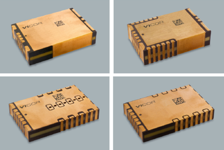
Figure 3: The new BCMTM, PRMTM and VTMTM rad-tolerant DC-DCs
1. A 300 W, 9 A, 849 W/in3, isolating, ZVS/ZCS, SAC Bus Converter Module (BCM3423PA0A35C0S) which accepts a d.c. source from 94 to 105 V and outputs a fixed load voltage 1/3 of the 31 to 35 V input. Maximum ambient efficiency is specified at 94% in a package size of 33.5 x 23.1 x 7.4 mm weighing 25.9 g.
2. A 200 W, 7.7 A, 797 W/in3, non-isolating ZVS buck-boost regulator, (PRM2919P36B35B0S) which accepts an input from 30 to 36 V and outputs an adjustable load voltage from 13.4 to 35 V. Its maximum ambient efficiency is specified at 96% in a package size of 29.2 x 19.0 x 7.4 mm weighing 18.2 g.
3. A 200 W, 50 A, 1204 W/in3, isolating, ZVS/ZCS, SAC DC-DC (VTM2919P32G0450S) which accepts input from 16 to 32 V and outputs a fixed load voltage of 1/8 of the input, ranging from 2 to 4 V. Its maximum ambient efficiency is specified at 93% in a package size of 29.2 x 19.0 x 4.9 mm weighing 11 g.
4. A 150 W, 150 A, 903 W/in3, isolating, ZVS/ZCS, SAC DC-DC (VTM2919P35K01A5S) which accepts input from 13.4 to 35 V and outputs a fixed load voltage 1/32 of the input, ranging from 0.42 to 1.1 V. Its maximum ambient efficiency is specified at 91% in a package size of 29.2 x 19.0 x 4.9 mm weighing 13.3 g.
The four DC-DCs have been designed using a redundant system architecture containing two identical parallel powertrains with fault-tolerant control to meet SEE requirements. To reduce manufacturing costs, the parts have been packaged in a plated, epoxy-moulded resin BGA with excellent thermal conductivity, branded as SM-ChiP, compatible with standard surface-mount, pick-&-place and reflow assembly processes. The DC-DCs are EAR99, specified from -40 to 125°C and offer various overvoltage, short-circuit current, undervoltage and thermal protection features. The target total-dose is 50 kRad (Si) with SEE and other reliability data to be released later this year.
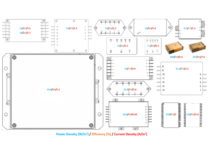
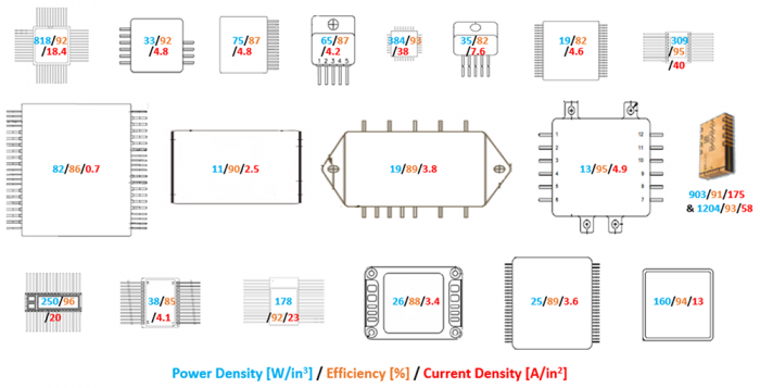
To highlight the superior densities offered by the new rad-tolerant DC-DCs, Figures 4 and 5 compare their relative sizes with existing space-grade switching POLs and isolated DC-DCs respectively. The power density of each convertor in W/in3, its efficiency in % and current density in A/in2, have been annotated in blue, orange and red respectively. A range of efficiencies are typically specified for different load conditions.
Click image to enlarge
Figure 4: Comparison of space-qualified switching POLs with the VTM2919s
Click image to enlarge
Figure 5: Comparison of space-qualified isolated DC-DCs with the BCM™ and PRM™
When compared with existing qualified converters, the new, rad-tolerant, COTS, SAC DC-DCs deliver major increases in output power, density and efficiency in a smaller volume and lighter form-factor. Regulated voltages are significantly cleaner with less bulk decoupling. Parts will have heritage from next year and evaluation boards are available.
Click image to enlarge
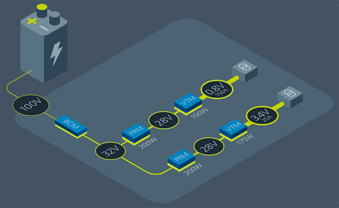
Figure 6: A modular 100 V power-distribution solution for spacecraft avionics


