Designing to Protect: Industrial Motor Drive Circuits

An overview of overvoltage protection devices that match motor drive circuit requirements
Figure 1: The 8/20 µs current waveform is widely used to test overvoltage devices and originates from UL 1449
Motor drive circuits employed in a wide range of today’s industrial, commercial, and consumer applications are responsible for controlling the speed, torque, and position of electric motors, enabling precise motion and energy efficiency. However, motor drives are often exposed to electrical threats such as overvoltage and overcurrent events, which can severely damage components, reduce system reliability, and cause costly downtime.
Overvoltage conditions can arise from external sources like lightning strikes, grid switching transients, or internal factors such as inductive kickback from stored energy in the motor windings. Therefore, to safeguard motor drive circuits, engineers understand the importance of implementing robust protection strategies. These typically include the use of surge protective devices (SPDs), voltage clamping components like metal-oxide varistors (MOVs), and gas discharge tubes (GDTs). Newer hybrid MOV and GDT component solutions or transient voltage suppression Power TVS (PTVS) diodes are now also considered in the robust protection arsenal.
This article details the leading types of protection components available that are known to offer effective defense against overvoltage threats. It also presents standards compliance tests typically used on these devices and advice on how evaluate each device for a given application. The practical design benefits protection solutions provide are critical to ensuring operational safety while minimizing maintenance costs and preserving the overall reliability of the electrical system.
Overvoltage Protection Compliance
An overvoltage transient is a sudden, short-duration spike in voltage that exceeds the normal operating levels of an electrical system. These transients can last from microseconds to a few milliseconds and are typically caused by everything from lightning strikes to the nearby operation of heavy machinery. Although brief, overvoltage transients can cause serious damage to electrical equipment, degrade insulation, disrupt operations, and shorten the lifespan of sensitive components. For the overall health and performance of electrical systems, it is crucial to mitigate these events.
Figure 1 introduces the UL 1449 standard 8/20 µs current waveform used by manufacturers to ensure compliance. This and several other waveforms exist to replicate overvoltage transients like lightning induced surges that couple to the AC grid.
With a typical design process, a motor drive will be incorporated into a system that also contains a programmable logic controller, power supplies, and other equipment that may serve the motor drive itself. These systems are typically mounted within an industrial control box and fed 3-phase 240 VAC or 480 VAC from an available AC grid transformer.
The First Line of Defense
For many industrial cabinet designers working with motor drives, the phrase “first line of defense” for overvoltage protection relies heavily on surge protective devices (SPDs). The features in SPDs not only protect the motor drive, but also many systems that are common within a full system solution.
The basic principle of an SPD is to limit the voltage that is applied to electrical equipment and systems to a safe level during transient overvoltage events. SPDs are typically installed at the point where electrical power enters a building or facility, which is commonly the main distribution panel or subpanels. They can also be installed at specific equipment locations to provide localized protection.
SPDs typically contain one or more surge protection components, such as Metal Oxide Varistors (MOVs) and Gas Discharge Tubes (GDTs). SPDs with MOVs are often designed with fail-open features. In the event of a catastrophic surge that exceeds the MOV’s capacity, the SPD disconnects the MOV from the circuit, preventing the surge from propagating further or entering a thermal runaway condition.

Click image to enlarge
The following are the basic steps in selecting the correct SPD for a system:
Step 1: Check for Safety and Compliance Standards
Step 2: Determine the Type of SPD Needed, Type 1 or Type 2
Step 3: Review Electrical Specifications
Step 4: Consider SPD Configuration and Power System
Step 5: Analyze SPD Features and Ease of Maintenance
Figure 2 provides a simplified flowchart.
The Second Line of Defense
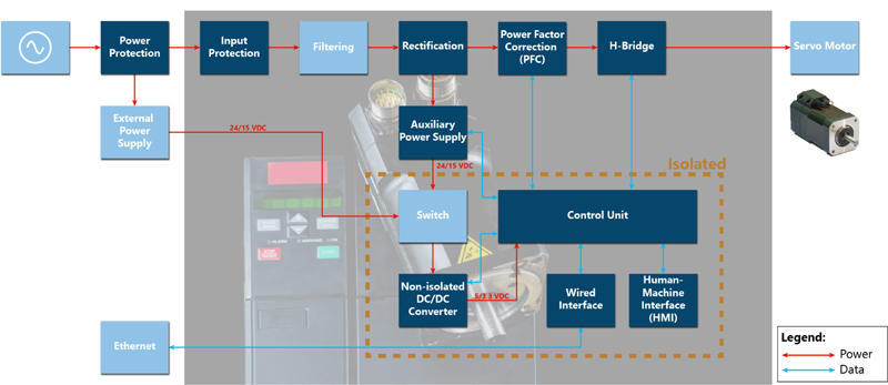
While selecting the right SPD lies with panel design engineers, the design for the physical motor drive is entirely different. Looking at a typical design for a motor drive in Figure 3 identifies the representative blocks within a motor drive application.
From Figure 3, the SPD previously mentioned lies within the block labeled, “Power Protection”. Typically, those designing the physical motor drive itself will not be inherently aware of the protection offered by the SPD at the feed-in from the AC grid. As a result, most motor drive circuits will have their own “Input Protection” block that accomplishes some form of overvoltage protection. This can be seen as a “second line of defense” and has discrete protection components that will include MOVs, GDTs, hybrid components, and power TVS diodes.
Click image to enlarge
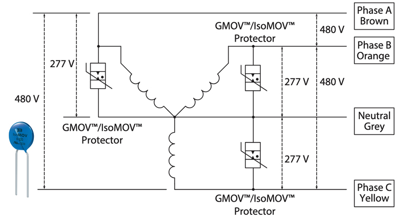
This front-end protection can be accomplished in a myriad of ways. A 3-phase fed system is commonly found in most motor drive circuits due to its cost-efficiency and load balancing advantages. GDT and MOV series combinations are generally used to provide robust protection against overvoltage transients in these systems. To save space and reduce component count, hybrid components such as Bourns® IsoMOV® and GMOV™ protectors that deliver the equivalent function of a discrete MOV and GDT in series to accomplish this task with a single solution. Figure 4 shows a 3-phase 480 VAC Wye configuration widely used as the input into a motor drive circuit.
Hybrid protectors also help motor drive designers better tailor the surge protection performance to their requirements, and enables them to include the GDT isolation without a PCB redesign.
Click image to enlarge
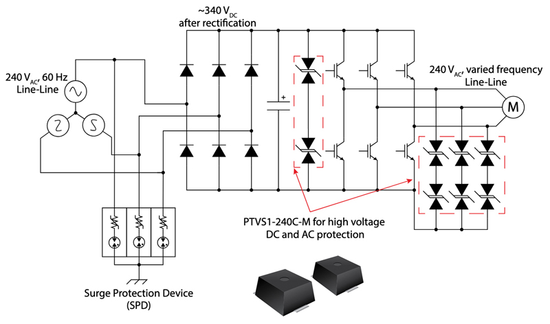
Besides GDTs, MOVs, and hybrid protection components, designers can also enlist the protection advantages achieved with power TVS diodes. These devices offer tighter clamping action with very quick response times and can absorb relatively high current. These devices are well-suited to protect very sensitive equipment compared to other options, which makes them great to incorporate in spots where sensitive components such as IGBTs and MOSFETs are susceptible to overvoltage conditions. It is common to see these devices being used as protection against inductive kickback from motor windings or on the DC bus to provide precise clamping within a certain tolerance. Figure 5 shows power TVS devices being used in a variable frequency drive (VFD) for both DC bus and motor winding protection.
Motor drive designs lend themselves to needing an overvoltage protection device that clamps with precision. IGBTs and MOSFETs being used as an H-Bridge will most often have maximum voltage ratings of 1200 V or less. With inductive kickback from motor windings, voltage transients in the kilovolts are frequent. Most designs incorporate a snubber network that include power TVS diodes to ensure a clamping voltage within a certain tolerance of the operating voltage. Typically, this will be much lower than the 1200 V.
Click image to enlarge
Many PTVS diodes on the market feature clamping voltages range from 10 – 470 V. For applications requiring TVS diodes that support higher voltage, the standard practice strings PTVS diodes in series to accomplish a much higher clamping voltage as seen in Figure 5. In that scenario, it is recommended to use two PTVS diodes that are rated for a continuous 240 V operating voltage where the DC bus is held at 340 VDC. Placing two of these power TVS diodes in series increases the available continuous voltage to ~480 V, which offers plenty of headroom for the DC bus to fluctuate, but also protects the IGBTs from experiencing voltages above their maximum voltage rating. The same logic applies for the motor side. If the output voltage is an expected 240 VAC output, two series connected PTVS diodes rated at 240 V will allow fluctuation to occur but clamps the output to 480 V in the event the motor produces voltage transients.
In addition, PTVS devices provide the capability to blur the line between a “second line” and “third line of defense”. They can be used as front-end protection as well, but typically reside in the mentioned spots for motor drive applications.
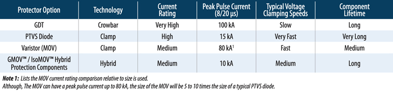
For all the mentioned technologies discussed, it can be difficult to understand the choices between certain components. Figure 6 is a helpful table for basic information on each discrete device that can help guide designers.
Click image to enlarge
Don’t Overlook Motor Drive Protection
Overvoltage protection is a crucial aspect of maintaining the integrity and performance of motor drive circuits. By effectively managing and mitigating the risks associated with transient overvoltage events, designing effective protection mechanisms help keep motor drive systems across various applications running reliably. From industrial automation to consumer electronics, the importance of safeguarding against overvoltage cannot be overstated.
Implementing robust overvoltage protection solutions helps prevent costly downtime, equipment damage, and potential safety hazards. As technology continues to advance, the development of more sophisticated and responsive overvoltage protection devices will be essential in adapting to increasingly complex electrical environments.
In conclusion, investing in high-quality overvoltage protection devices is a smart proactive design measure to maintain optimal performance and long operation life of motor drive circuits.


