Solving Multiphase Power Challenges in Compact, High-Efficiency Systems with Coupled Inductors

Modern power systems must operate more efficiently in less space, with tighter thermal constraints
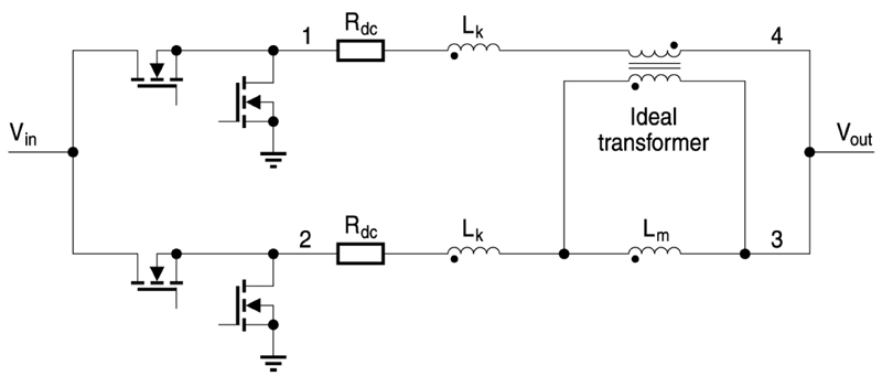
Figure 1: Simplified equivalent circuit for simulation
Whether in data centers, electric vehicles, or industrial automation, engineers face increasing demands to deliver higher power with less space while minimizing losses all while managing thermal loads without complex cooling infrastructure.
A central trend in these applications is the adoption of 48-volt power distribution. Demands from AI computing, edge processing, and high-density storage have pushed board-level power requirements into the kilowatt range. Systems that once operated exclusively at 12 volts are now deploying 48-volt distribution to reduce losses and improve scalability.
Originally confined to the telecom sector, 48-volt architecture is now gaining traction in high-performance computing and next-generation vehicles. It enables lower current for the same power level, which reduces resistive losses, allows for thinner cabling, and improves overall energy distribution efficiency. However, efficiently stepping down from 48 volts, typically first to 12 volts, then to intermediate rails like 9.6, 8, 6, or 4.8 volts, and ultimately to point-of-load voltages as low as 1 volt, has become a critical design priority.
Like server systems, which must deliver kilowatts of power within tightly packed rack units and with limited airflow, automotive designs face significant spatial and thermal constraints as they integrate 48-volt subsystems for power steering, braking, and turbochargers alongside legacy 12-volt systems for lighting, infotainment, and control modules. As next-generation vehicles introduce 48-volt subsystems, they must still support legacy 12-volt electronics, such as infotainment, lighting, and body control modules. This requires compact, thermally stable converters capable of managing bidirectional energy flow across vehicle power systems. The converter’s performance depends heavily on the inductors used in each phase, making inductor selection a critical step in meeting design objectives.
But delivering regulated 12-volt and sub-12-volt rails from a 48-volt source, especially at high currents, poses significant design challenges. These include the physical footprint of multiphase converter stages, the efficiency of power delivery, and the difficulty of dissipating heat in dense, often passively cooled environments.
One of the most effective ways to address these challenges lies in the design of magnetic components. Specifically, coupled inductors have emerged as a powerful solution for reducing board space, improving efficiency, and supporting scalable multiphase power stages. Among these, the TDK ERUC23 coupled inductor offers a practical, high-performance option for engineers designing within real-world constraints.
This article examines three key design strategies for today’s power engineers and how components like the ERUC23 support these goals. These strategies include reducing size while boosting efficiency through coupled magnetics, enabling reliable power delivery in 48-volt systems through smarter step-down designs, and improving thermal performance by minimizing losses at the component level.
Click image to enlarge
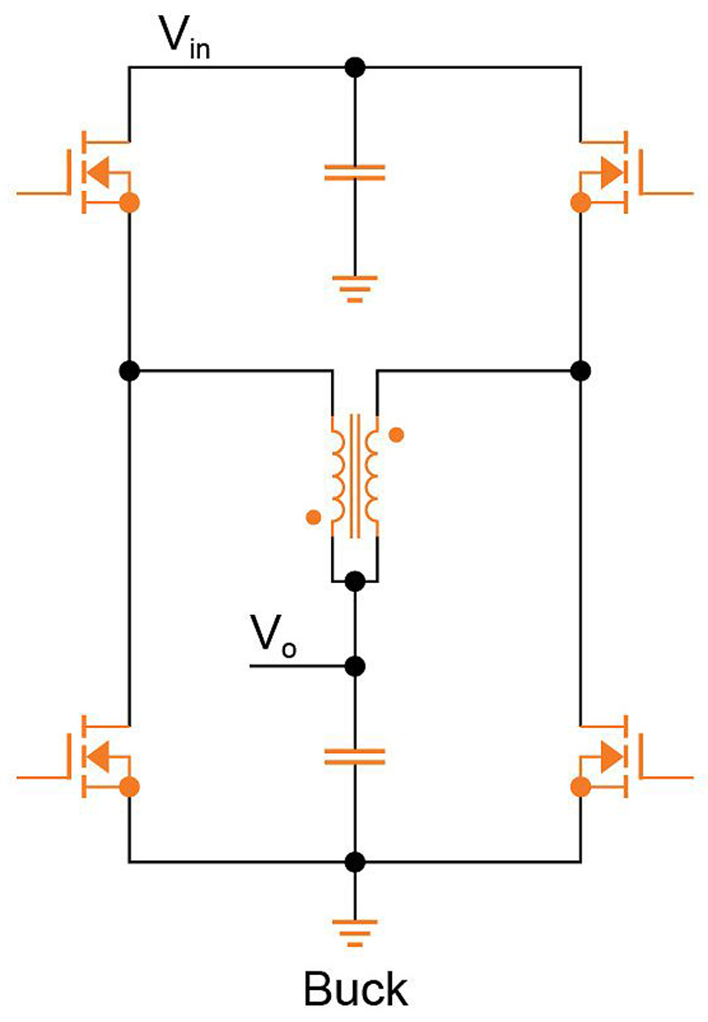
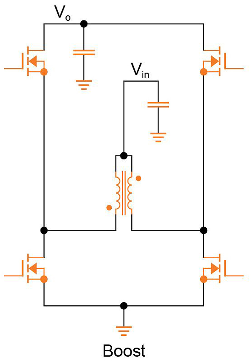
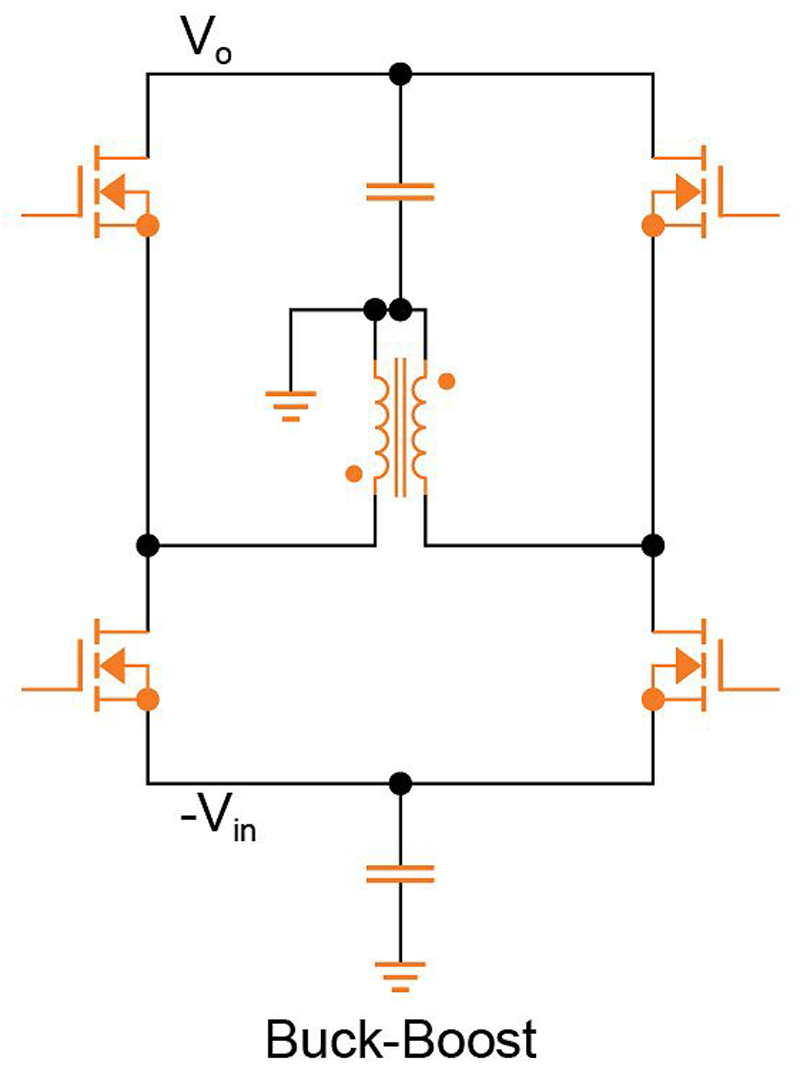
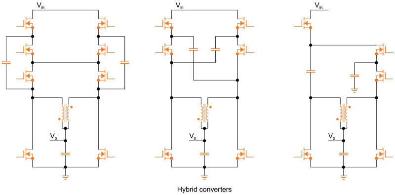
Figures 2a, 2b, 2c, & 2d: Typical topologies include buck, boost, buck-boost, and hybrid converters
Coupled Inductors Enable Major Size and Efficiency Gains
As power requirements rise, adopting multiphase converter architectures is an attractive option for distributing current across multiple channels while improving both thermal performance and transient response. While effective, these designs typically require one discrete inductor per phase. In high-current systems with four, eight, or even sixteen phases, this quickly becomes a layout constraint, consuming board space and complicating routing and cooling.
Coupled inductors offer an elegant solution. By using a single magnetic core to support two windings, these components allow engineers to replace two discrete inductors with one compact package. The result is a significant reduction in physical footprint, by some estimates, as much as 70% compared to a pair of separate inductors performing the same function. This footprint reduction frees up space for other critical components or enables smaller overall designs without sacrificing power capability.
Beyond size reduction, coupled inductors also improve electrical performance. Their shared magnetic core promotes ripple current cancellation between phases, which reduces the total ripple current seen by the system. Lower ripple current decreases losses on the switching devices (MOSFET, GaN). In addition, a coupled inductor typically experiences lower core and copper losses than a solution using two separate inductors under the same load conditions, thanks to better magnetic coupling and ripple current cancellation between phases. These lower inductor losses are complemented by reduced switching losses in the semiconductors, due to the decreased ripple current. Together, these effects contribute to overall efficiency gains that are particularly important in systems specified to operate near or above 95% efficiency.
In modern designs, even minor improvements in efficiency matter. A 0.2% gain in power efficiency at a baseline of 95%, for example, reduces the losses by 4%, improving thermal headroom and extending the life of system components. Across large-scale deployments, such as hyperscale data centers or vehicle fleets, these fractional gains add up to meaningful improvements in system performance and operating costs.
A Practical Example: The TDK ERUC23 Coupled Inductor
How these design principles can be applied in practice is demonstrated in the following with the TDK ERUC23 coupled inductor. Engineered for use in high-efficiency multiphase systems, this component features a flat-wire winding structure that supports high saturation current while maintaining low DC resistance. This structure enables high power delivery in a compact form factor without excessive thermal rise.
Each ERUC23 is designed to support a two-phase configuration. Engineers can combine multiple units to create four-phase, eight-phase, or higher-order converter stages, depending on system requirements. This modular approach simplifies design and supports a wide range of applications, from high-performance computing to automotive powertrains.
The ERUC23 is qualified to AEC-Q200 standards, making it suitable for automotive use cases that demand robust thermal as well as mechanical performance. It is also ideal for industrial systems that must operate reliably in thermally constrained environments. The component’s compact footprint of 26.8 x 13 mm and high current-handling capability up to 97 A make it a compelling choice for designers seeking to reduce system size while increasing output power.
By reducing the number of components required and enhancing electrical efficiency, the ERUC23 facilitates simpler board layouts, enabling engineers to meet stringent thermal and spatial constraints without compromising performance.
Thermal design is often the limiting factor in high-power systems. As power density increases, it becomes more difficult to dissipate heat using traditional methods. Forced-air cooling adds complexity and noise, while liquid cooling introduces additional cost and design overhead. Wherever possible, designers seek to reduce thermal load at the source, often by increasing conversion efficiency.
Click image to enlarge
Figure 3: Connection – single inductors do not have polarity, but the connection is important to get the right performance for a coupled inductor. Pin 1 & 2 should have the same functionality, pin 3 & 4 have the same functionality.
Click image to enlarge
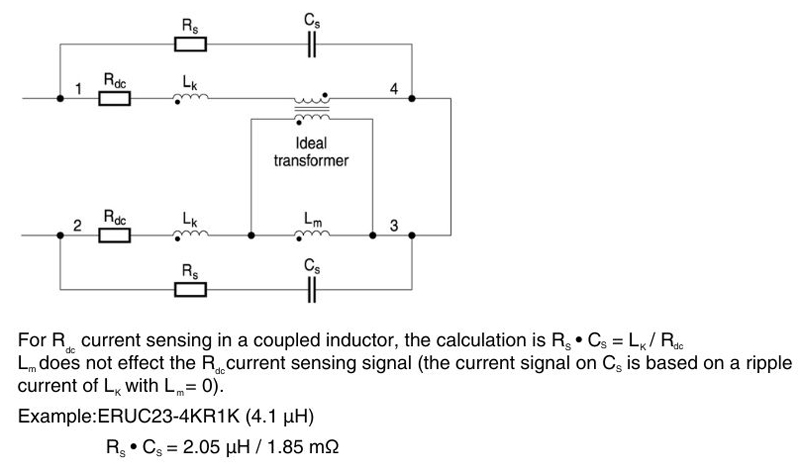
Figure 4: Rdc Current sensing with RC filter
Conclusion
Power engineers are under increasing pressure to deliver more performance within tighter constraints. As power demands rise and the 48-volt architecture becomes more common, traditional component choices are no longer sufficient. Coupled inductors offer a powerful alternative, combining compact size with electrical efficiency and multiphase scalability.
By replacing discrete magnetics with shared-core components, engineers can reduce footprint, improve layout, and minimize ripple current, ultimately increasing system efficiency and easing thermal design. The TDK ERUC23 coupled inductor serves as a strong example of how these benefits come together in a real-world component.
In the evolving landscape of power electronics, the path forward is clear: smarter architectures, higher efficiency, and compact components that enable tomorrow's systems to succeed within today's limits.


