Determination of the Ideal Power Inductor for Energy-Efficient Applications
The basis for energy-efficient devices is influenced by the power supply
Energy-efficient devices are important components for saving resources and protecting the environment. The more efficient the electronics, the longer the battery service life for mobile devices - and in large-scale industrial and server installations with thousands of loads, the energy requirement is markedly reduced. The basis for energy-efficient devices is essentially influenced by the power supply unit. While the linear regulators still most widely used in the past were voltage regulators, mainly switch mode power supplies are found in modern power electronics. The continuous reduction in processor voltages has played its part in this. A few years ago, switching frequencies up to 300 kHz were widespread, whereas modern switching controllers usually clock with frequencies of 800 kHz and more. The switching losses, on the one hand, but also the power inductor losses, on the other, are important aspects in the design of switching power supply units. New iron alloy group material compositions have further reduced core material losses for high current power inductors. WE-MAPI is a component series whose adept material selection and manufacturing technology combines the optimal use of inductance and current carrying capacity with low internal losses. The Online platform REDEXPERT - based on a metrological procedure - helps the developer determine the hitherto most accurate data for DC and AC current losses in power inductors in the application environment. Core loss calculations based on Steinmetz equations very soon reach their limits here.
WE-MAPI Structure and Properties
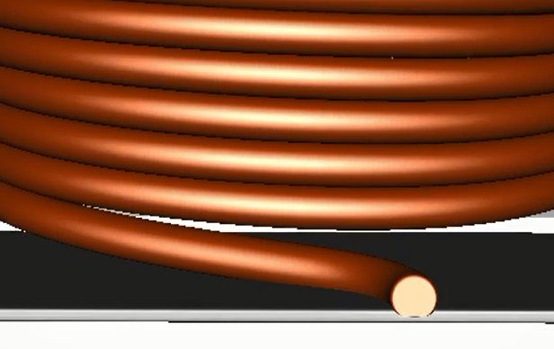
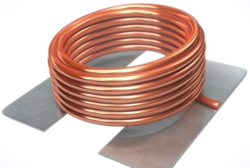
WE-MAPI is the latest and most innovative series of coils from Würth Elektronik. Conventional coils mostly use enameled copper wire wound around the core and soldered or welded to the terminal with a clip. The outer shielding ring is then mounted and bonded with the inner core andthe winding.

Click image to enlarge
Click image to enlarge
Figure 1a & 1b: View of the WE-MAPI and the direct contacting of the wire with the connection pads
WE-MAPI breaks new ground and the winding is contacted directly with the component'sconnection pad without soldering and welding. Saving the clip allowed the effective diameter to be increased, which means fewer windings are needed for the same inductance values. This is directly expressed in a considerably reduced DC resistance (RDC) of the winding. In the application, the start of the winding of the coil is usually connected with the switching node of the switching controller – a marking on the component indicates this. Consequently, the spatial expansion of the "hot" switching node is minimized and coupling effects through the outer part of the winding at a "stable" potential are also shielded.
Click image to enlarge
Click image to enlarge
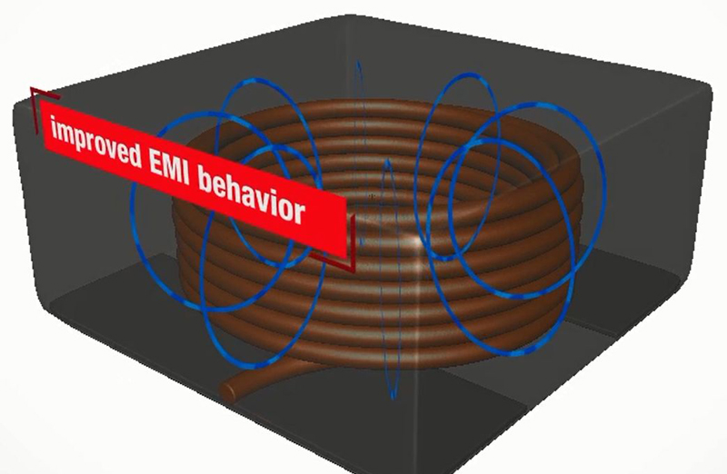
Figure 2a & 2b: Self-shielding winding and core design for improved EMI behavior of the WE-MAPI series
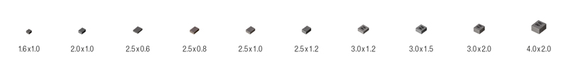
The core consists of an innovative metal alloy pressed around the winding. This confers the WE-MAPI series high inductance values with a small package size. At the same time, the special construction of the core has a self-shielding effect. The core material itself is temperature stable with only a slight drift and "soft" saturation behavior. A protective layer is also applied around the core rendering the surface resistant against environmental influences. The WE-MAPI series components are available in many different package sizes from 1.6² x 1.0 mm, up to 4.0² x 2.0 mm.
Click image to enlarge
Figure 3: Overview of the available package sizes for WE-MAPI
Losses in Power Inductors
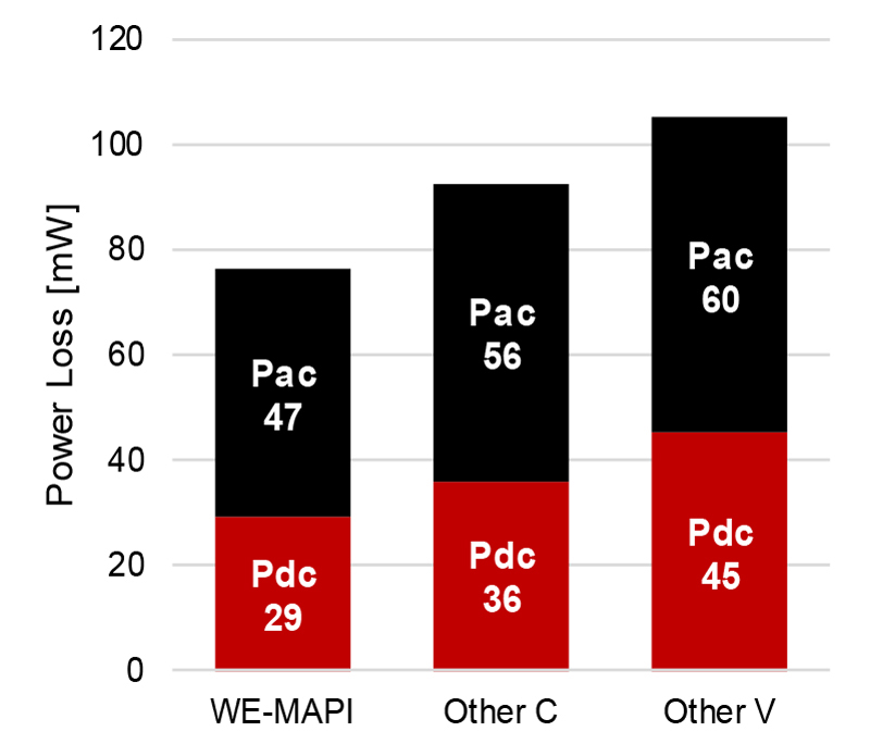
The losses of a power inductor arise from core material losses and winding losses. The winding losses themselves can be divided into DC current losses, essentially influenced by the DC resistance of the winding P = I² ×RDC and the AC losses (RAC) of the winding that arise from skin and proximity effects. Several methods are available to determine AC losses of the winding, e.g. the Dowell, Ferreira or Nan/Sullivan methods. The importance of AC losses in modern switching controllers can be ascertained with a simple set-up and measurement of the relevant losses. As an example, we take a buck converter with an input voltage of 24 V. At the output there is 12 V with 2 A. The clock frequency is 500 kHz. In Figure 4, a WE-MAPI 4020 series power inductor with 2.2 µH is compared with power inductors of the same package size. It is clearly apparent that with all the coils measured, the AC losses outweigh the DC losses.
Click image to enlarge
Figure 4: AC and DC losses of a 2.2 µH coil, buck converter with 24 V to 12 V, 2 A, 500 kHz
The coil is one of the most important components in switching controllers. Accurate determination of the losses and heating is therefore a critical step in the selection of the right component. In order to be in a position to predict heating, the AC losses firstly have to be accurately determined.
The Steinmetz Models
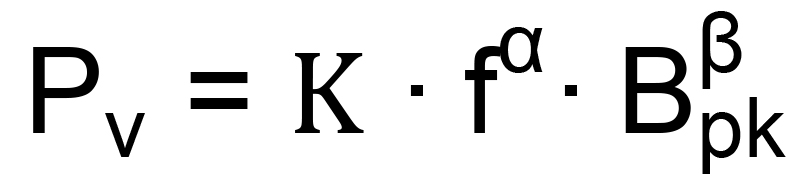
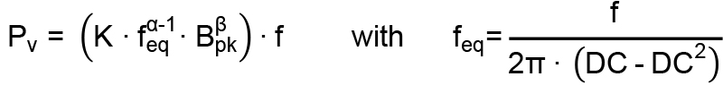
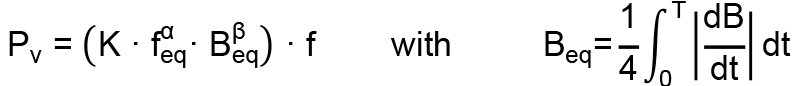
Viewed historically, core losses were determined with the Steinmetz Model (1) and later with the Modified Steinmetz Model (2) or the Generalized Steinmetz Model (3).
Click image to enlarge
Equation 1
Click image to enlarge
Equation 2
Click image to enlarge
Equation 3
Whereby PVare the core losses per unit volume, fthe switching frequency, and Bpk the magnetic sinusoidal modulation.feqis the equivalent frequency that results in non-sinusoidal modulation for a deviating duty cycle. K, aand bare the constants of the core material determined by extensive measurements with a ring core. The essential drawback of the Steinmetz equation is that it mainly applies for sinusoidal excitations and determination of the coefficients is usually only measured with small signals. However, in most applications in power electronics, the coil current is not sinusoidal. In addition, the currents are large signals of several mA up to several hundred Amperes. There are also other models that attempt to resolve the problem of non-sinusoidal waveforms by separating hysteresis and eddy current losses. Here the empirical Steinmetz equation has proven to be a useful variant, but it only offers high accuracy for sinusoidal currents. However, the various Steinmetz models only work optimally with a duty cycle of 50 % and within a restricted frequency range. In addition, on account of the high complexity in finding the magnetic path length, the determination of core losses with the help of existing models for iron powder and metal alloys is not only demanding, but the accuracy is also subject to serious fluctuations. Moreover, for inductors that consist of several different core materials, estimation of the losses is only possible with great effort, if at all.
The Würth Elektronik Model
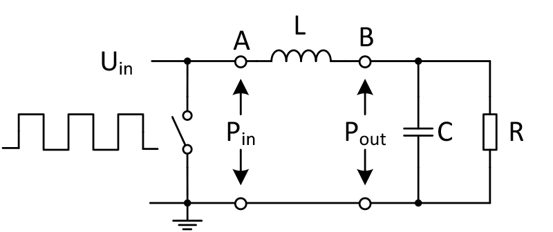
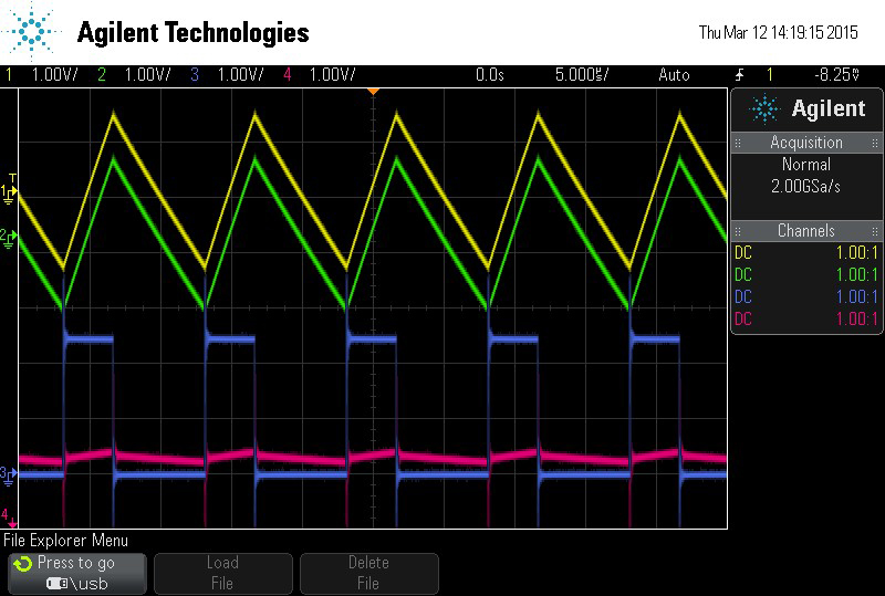
Würth Elektronik eiSos has developed a highly modern model capable of accurately determining the complete AC losses in inductors. This model is based on empirical data obtained with a real-time application set-up. Here the total losses of the inductor are divided into AC and DC losses. Empirical data are measured with a DC/DC converter, as presented in Figure 5. A pulsed voltage is applied to the inductor, whereby the input power PIN and the output power POUT are measured. PLOSS = PIN - POUT is determined on this basis and the AC losses of the coil PAC are separated. This procedure is used to measure the different parameter settings – such as fluctuations in the magnetic modulation, switching frequency, ripple current, etc. – and this empirical data is recorded. With the help of this empirical data, the model is created for calculation of the AC losses PAC = f(ΔI, f, DC, k1, k2).
Click image to enalrge
Click image to enlarge
Figure 5a & 5b: Set-up of the DC/DC converter for determining loss and the associated oscilloscope recordings
Advantages of the Würth Elektronik AC loss model:
- The empirical data is based on a DC/DC converter
- Accurate determination of losses for every given duty cycle
- Accurate across a wide frequency range (10 kHz to 10 MHz)
- Also considers the smallest changes in the core material and the winding structure
- Applicable for components with more than one material used
- Accurate determination of losses in components with iron powder and metal alloys
- Applicable for every possible core design and winding structure
- Also includes AC winding losses
Performance of the Würth Elektronik Model
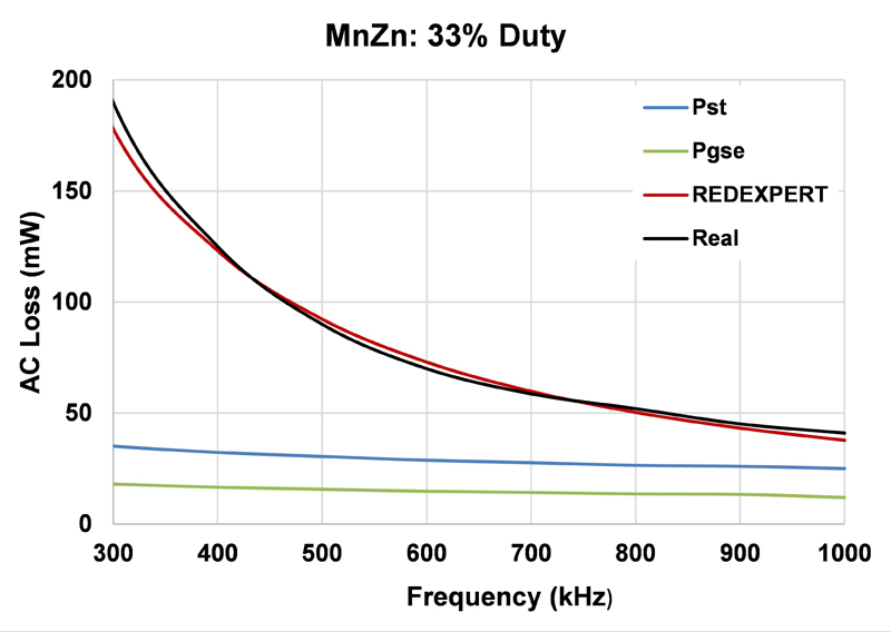
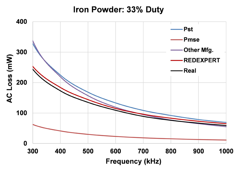
The model from Würth Elektronik has been extensively validated and compared with existing models and measured data. AC losses for different materials, such as WE-Superflux, iron powder, NiZn, MnZn, etc. have been measured over wide duty cycle and frequency ranges and compared with theoretical models (Figure 6). The following graphs show the core losses determined with the Steinmetz power equation (PST), Modified Steinmetz equation (PMSE) and the Generalized Steinmetz equation (PGSE). REDEXPERT shows the AC loss following calculation with the AC loss model from Würth Elektronik. The measured AC loss is “Real”.
Click image to enlarge
Click image to enlarge
Figure 6a & 6b: Inductor made of MnZn and iron powder at 33% DC
Determining Losses with REDEXPERT
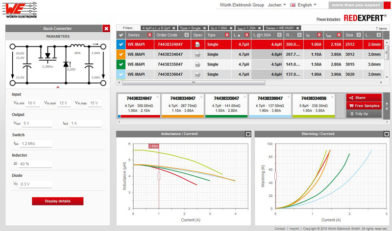
REDEXPERT is the new online design tool from Würth Elektronik eiSos used to select a suitable power inductor for the respective application. REDEXPERT is an easy-to-operate and effective tool, enabling components to be compared and selected within the shortest time. Firstly the user enters the input and output parameters for the required topology. REDEXPERT then calculates the necessary inductance value and displays the suitable inductances. Figure 7 shows the REDEXPERT screenshot.
Click image to enlarge
Figure 7: Simulation of a buck converter in REDEXPERT with WE-MAPI components
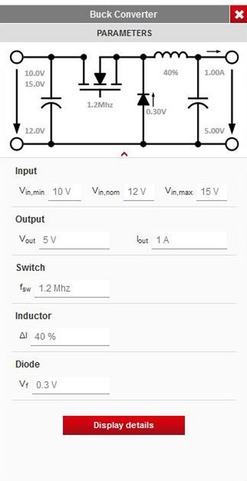
The calculation of AC losses in a magnetic component is just as critical as it is complex, but not with REDEXPERT, as the new AC loss model from Würth Elektronik is integrated. Based upon accurate calculation of the complete AC losses, the application is also suitable for temperature estimation. Currently REDEXPERT supports three topologies in which the component can be selected for the application: buck, boost and SEPIC converters. The losses are displayed graphically over the complete input voltage range in order to also take extreme scenarios into consideration. This way the most energy-efficient power inductor for the respective application can be selected in next-to-no time. In order to determine the right inductor for a buck converter, enter the existing input voltage range and the output voltage and current in the input screen (Figure 8), as well as the switching frequency, the diode flow voltage and the targeted ripple current of the inductor. By clicking on "Display details", the suitable power inductor is obtained, including its anticipated ripple currents and the losses in the application.
Click image to enlarge

Click image to enlarge
Figure 8a & 8b: Defining the buck converter and the losses of the selected inductor
There is also a manual loss calculator, which calculates the losses for power inductors independent of the topology. Only the frequency, the duty cycle and the ripple current, or the voltage drop, have to be entered, and REDEXPERT takes care of the rest. One practical aspect is that the entries are immediately displayed in graphic form below the entry screen. REDEXPERT is a web-based tool, i.e. the user has neither to download REDEXPERT nor worry about updating. Registered customers benefit from further advantages, e.g. determination of inductance value or temperature increase of the inductor for every possible current value.
Summary
The WE-MAPI power inductors offer maximum power in the smallest of spaces. With the innovative core material and the sophisticated design, new standards have been set. For energy-efficient switching controllers, the WE-MAPI is best selected with REDEXPERT, the new online design tool from Würth Elektronik. This integrates the world's most accurate AC loss model, which renders the parameters of frequency, ripple current and duty cycle with high accuracy over a wide range of values.