Digital power management without code qualification
There are many different styles of digital power management available
Digital power management has become more popular year over year, for multiple reasons. There are more semiconductors available to support digital power management, helping reduce the cost for such solutions. Another important reason for today’s success of digital power management however, is the increased trust and better understanding of digital power management by power supply design engineers.
There are many different styles of digital power management available today, defined by how the digital functionality is implemented. Microcontrollers, microprocessors, DSPs and even FPGAs can be used. Within each ‘style’ there are products available which suit themselves to do digital power management. Devices are suitable if they have enough data crunching power and the right analog interfaces. Data crunching power is usually not difficult to find, analog interface ability however needs to be dedicated for the purpose of power supplies.
These interfaces include analog to digital converters (ADCs) as well as PWM generators. These have to be fast and accurate enough so that the power supply can operate with a stable control loop and so that it has an acceptable line and load transient response. Adding such analog interfaces to a digital core product with external, discrete ADCs is possible but usually quite expensive, space intensive and challenging to implement.
The difficulty lies in the fact that the selection of suitable components is difficult and requires power supply system knowledge as well as a good understanding of ADCs.
A much simpler and often more optimized path is to select an integrated circuit dedicated for digital power management. Today a broad selection of such devices exists in the market.
Solutions with coding and code qualification
The group of available solutions requires the digital circuitry to be programmed by code. Often C code is used. Such coding allows for the greatest flexibility. Every possibility a designer would want to do can be implemented as long as the processing power of the digital circuitry and the analog interface permits it. This enormous flexibility comes at a certain cost. Programming knowledge is necessary. Usually power supply experts are not very experienced in programming code. Sometimes development teams consist of analog power supply experts as well as software experts. While such a development team setup may work well, very often there are difficulties with communication within the team. Often the software programmers do not know power management well enough to find suitable solutions quickly.
After code programming is completed, a rigorous testing procedure needs to be run. A stuck software routine or undefined states can be catastrophic in power supplies. Verification and also qualification of such software is time consuming, costly and requires experience. In many engineering fields such as automotive, military but also in industrial applications, any code modification will start a new cumbersome qualification process. These disadvantages limit such digital power management solutions to special cases where a highest degree of freedom is necessary and no standard solution is available
Solutions without coding but with code qualification
Some vendors of digital power management integrated circuits help their customers in the design process by offering pre-programmed software tools. This can be coded IP generated specifically for power supply functions which is provided to the power supply design engineer. The designer can then combine some of these program modules and configure the complete solution. Such software support may also consist of graphical user interfaces (GUIs) that can be quite easy to use. These significantly help power supply designers to set the digital power supply to do what it needs to do. They perform the translation from the way power supply engineers think to how digital circuitry needs to be told what to do. While this is a valuable support vehicle, the outcome of such tools is software code after all.
With this approach the flexibility of the design engineer is somewhat limited. If the pre-programmed software tool does not allow a certain function, it cannot very easily be implemented. While the generation of the code has been simplified, still extensive tests need to be performed to make sure that the power supply will work reliably. Also the final code needs to undergo the rigorous qualification process as mentioned above.
Solution without coding and without code qualification
The third style of how digital power supplies can be build is a hardware-coded system based on a state machine controller IC. Such a system comes pre-configured. The influence a power supply designer has on the controller is reduced to setting registers in the state machine. While this limits the flexibility somewhat, most possible use cases have been considered, when the controller IC was designed so that most applications will work very well with such an integrated approach. Also these natural limits make it much easier and safer to work with this controller. If only a limited amount of ‘adjust knobs’ are available, checking for errors becomes simple.
Figure 1shows a typical circuit with the ADP1051 fully integrated digital switching DC-to-DC controller IC based on a state machine. It is used in a full bridge topology intended for isolated DC-to-DC conversion of a few hundred Watts.
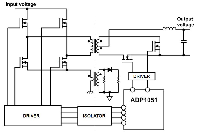
Click image to enlarge
Figure 1. ADP1051 in a zero voltage switched isolated DC to DC conversion topology with synchronous rectification
Graphical user interface and generated register settings
Figure 2shows a screenshot of the graphical user interface (GUI) of the ADP1051. While an I2C data stream may set the register settings of the state machine, such a GUI significantly simplifies the process. On different screens, all the possible settings can easily be made. In a spy window the user has full visibility of the data flow in between the GUI and the controller chip. The specific screenshot in Figure 2 shows the setting of the compensation of the control loop as an example. Poles and zeros can be relocated by the click of a mouse button. Different compensation schemes for different operating conditions are possible.
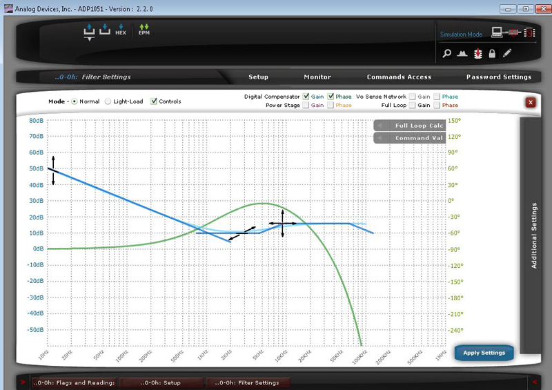
Click image to enlarge
Figure 2. Screenshot of graphical user interface for digital DC to DC controller based on state machine
Details about typical designs
The circuit shown in Figure 1 uses an ADP1051 controller from Analog Devices for a full bridge DC-to-DC conversion. Other typical applications are half bridge, two switch forward, and active clamp forward topologies. Even LLC resonant mode is supported by these controllers. For non-isolated power supplies, the new ADP1055 can be used in interleaved synchronous buck regulators for highest flexibility.
Further available controllers using the same concept are the ADP1047 / ADP1048 for power factor correction (PFC) applications.
All these solutions offer I2C or even PM-bus interfaces. These are used to dynamically read information about fault states or real time information about voltages and currents in the system. The digital interface is also used to set and reset certain register values. For easy design, all of the state machine controllers include an EEPROM that stores the register values. This enables simple start-up of the circuitry. A few of the EEPROM bytes can even be used for external data such as a system operation hour counters. An external flash memory or additional EEPROM is not necessary.
The integrated ADC and PWM generators are optimized for the usage in power supplies. The output voltage is sensed with both, a very fast ADC for best regulation loop bandwidth but also a very accurate ADC for good DC accuracy. The result of both ADCs is then combined in the digital domain. The power supply designer does not have to worry about these functional blocks. Figure 3 shows the integration of carefully selected analog circuitry and how it is combined with an EEPROM and digital control circuitry based on a state machine.

Click image to enlarge
Figure 3. Integration of the analog interfaces with the digital controller core
Specific advantages in industrial power supplies
Digital power supplies are especially common in telecommunications infrastructure applications. Already years ago, the many unique functions and features of digital power supplies offered clear system value. In Industrial power supplies, we are still at the beginning of the deployment curve. The drivers are machine-to-machine communication and the desire to communicate the status and conditions of the power supply itself as well as the quality of the generated bus voltages and the quality of incoming AC or DC voltages. Efficiency demands and reliability concerns are also a strong driver for digital power management in industrial applications. Digital power controllers based on a state machine offer ease of use and a low investment threshold to make it all happen.


