Eliminating the EMI Design Cycle in High-Voltage Defense Power Systems

New Vicor pre-certified DCM9223 DC-DC converter and filter reduce time and risk
Today's defense electronics need high-voltage-to-SELV conversion at unprecedented power levels and board densities. The specific challenge is converting 270V to a 28V or 48V bus while still meeting MIL-STD-461 conducted emissions limits (EMI), a requirement that is both a technical problem and a program schedule risk in equal measure.
Most design teams only encounter this EMI qualification at a later stage in the design cycle, after they’ve already locked in their converter architecture. At this point, should the system fail compliance, any required changes significantly drive up costs and delay schedules. Ultimately, choosing the right converter from the outset can determine how difficult and expensive the path to MIL-STD-461 qualification will be.
One way to eliminate the qualification risk is by choosing a pre-certified converter and companion filter solutions for MIL-STD-461 certification. Then designers can be confident that their systems will achieve first-pass compliance and avoid disastrous late-stage costs and delays.
Identifying the dual EMI pain points in high-voltage power buses
● CE101:targets conducted current from 30Hz to 10kHz, the frequency range where converter switching fundamentals and their subharmonics appear on power input lines.
● CE102: conducted voltage from 10kHz to 10MHz, covering the switching harmonics that propagate back toward the input source (Figure 1).
For a converter operating at several hundred kilohertz, the harmonics that land in these test windows are a direct and predictable consequence of the switching topology. As a consequence, any high-density defense converter will generate them regardless of how engineers design the downstream circuit.
Unfortunately, the severity of the problem scales with power level. At kilowatt-class output, common-mode and differential-mode currents on the input lines grow proportionally larger with each increment of output power. For example, a 1 or 2.5kW bus drives significantly larger emissions than a low-power design using the same topology. And, at those magnitudes both current modes become harder to suppress without purpose-designed filtering. The converters best suited for high-power defense applications therefore face the most demanding conducted emissions profile of any design category.
Meanwhile, size, weight and power (SWaP) constraints in aerospace and marine platforms compound the problem. Since every kilogram of additional filter mass directly increases the system weight budget, those same filtering components compete with signal-processing hardware and structural elements for board space. As a result, most defense programs cannot use traditional, bulkier filtering solutions, or else they must sacrifice size and cost to meet MIL-STD-461 compliance.
Why discrete EMI filter design is vulnerable
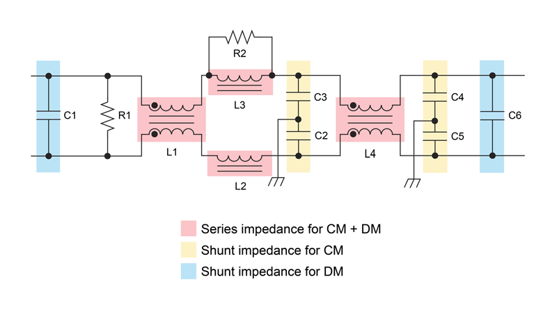
When designing custom, discrete filters for a 270V defense application, engineers must complete a highly interconnected, complex series of design steps that include custom component selection, multi-stage LC network design and PCB layout (Figure 2).
Click image to enlarge
Figure 2: Multistage filter showing the numerous components, including bulky inductors, required to filter out both common- and differential-mode noise for MIL-STD-461 compliance
While component selection and LC network set the filter's theoretical attenuation profile and frequency response, PCB layout ultimately controls how it behaves in the real world. Layout parasitics and stray inductance, capacitive coupling between traces and ground plane impedance move the filter's frequency response away from the simulated result. A filter that passes in simulation can fail at the test range because of these effects, and no reference layout transfers to a new board. Effectively, each new design entails a new filter characterization effort.
Initial test failure is therefore a common outcome for custom filter designs, and its impact is tangible.
A single conducted emissions test at an accredited facility costs $5,000 to $10,000 in lab fees alone, and that figure does not include the board respins that a failed result requires. Meanwhile, board fabrication takes three to six weeks per iteration, and most programs run two to four test cycles before achieving a passing result. For a program with a fixed delivery schedule, each additional iteration adds both cost and schedule impact, moving the delivery date and compressing the downstream integration timeline in proportion to the number of cycles required.
What a companion filter module can deliver
Instead of pursuing discrete filter designs, engineers can benefit from working with suppliers that offer pre-optimized, companion filters for their converters.
A companion filter is one that designers optimize to work alongside a specific converter, targeting its unique noise signature rather than that of a generic 270V source. By developing and characterizing the filter alongside a known converter, designers can tune its topology to the exact common- and differential-mode noise it produces over its full operating range. In turn, designers can deliver filters that meet CE101 and CE102 at the module level before the solution ever reaches a system board, with qualification data generated against a known, controlled noise source rather than an assumed one.
Module-level qualification also changes the compliance picture for system integrators. Because regulators characterize and document CE101 and CE102 compliance at the module level, that qualification transfers directly to the system. Teams that deploy a pre-characterized companion filter do not need to execute an independent EMI test campaign for the filter stage. The compliance evidence arrives with the module, and system integration proceeds from a known-compliant baseline instead of an untested starting point.
For that baseline to hold at the system level, the companion filter must also share the converter's footprint and thermal interface. A filter with a mismatched footprint forces the system integrator to accommodate two different mechanical profiles and two separate thermal paths, defeating the integration benefit.
Good practice is to use conduction-cooled baseplates, which match the converter's mating surface to concentrate heat at a single flat interface for coldplate or heat sink transfer and preserve power density. A dual benefit is that such a metal enclosure around the filter circuitry can contain radiated emissions without requiring board-level shielding.
Achieve first-pass compliance with drop-in high-density DC-DC converter and filter
Understanding these challenges and requirements, Vicor offers a set of pre-certified converter-companion filter pairs to help military and defense designers achieve first-pass compliance.
For example, the Vicor DCM9223 is an isolated, regulated DC-DC converter that accepts 160 to 420V at the input and delivers a regulated 28 or 48V bus at the output. With a footprint as small as 92.2 x 23.1 x 7.5mm and a weight of 70g, the module still delivers up to 2.5kW of power at 96% peak efficiency.
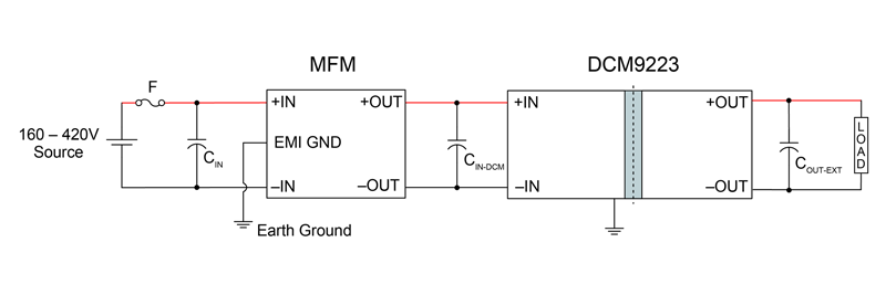
Alongside the DCM9223, Vicor offers the MFM4920* companion EMI filter, which is pre-characterized to meet CE101 and CE102 of MIL-STD-461E/F/G (Figure 3). Accepting 120 to 420V input, the filter covers both 270V nominal MIL-STD-704F sources and the full source transient window defined by the standard. Meanwhile, the filter operates from –55 to +125°C and carries a 1,800V dielectric withstand rating, making it suited to the full temperature range of airborne and shipborne military platforms. Even at these temperatures, designers can parallel DCM9223 and MFM4920 pairs to reach up to 10kW output power without redesigning the converter stage.
Click image to enlarge
Figure 3: The MFM4920 filter* connects directly upstream of the DCM9223, forming a complete 160–420V power conversion front end in two modules. Because Vicor characterizes the pair together against MIL-STD-461 CE101 and CE102, the compliance data engineers receive reflects the real-world behavior
The filter also comes in a metal enclosure that closely matches the DCM9223's footprint. The enclosure includes a conduction-cooled baseplate that shares the converter's thermal interface for direct coldplate mating, alongside a Parylene conformal coating for environmental protection. Such a paired enclosure and baseplate design lets designers integrate the filter into the same mechanical and thermal solution as the converter, with no additional accommodation required.
Together, the DCM9223 and MFM4920 deliver a pre-certified, screw-down solution. With it, designers can implement a compliant 270V-to-SELV conversion stage without custom filter design, layout iteration or dedicated MIL-STD-461 test campaign before first-pass system integration.
Reducing risk with pre-qualified building blocks
MIL-STD-461 compliance has historically cost significant time and money for every new power design and program. A pre-certified converter-and-filter pairing transfers that qualification burden to the module vendor, so the system integrator can confidently deploy a compliant solution rather than designing one from scratch. This eliminates project risk and time-to-market.
As defense platforms demand more power from smaller, lighter electronics, teams that adopt qualified building blocks like the Vicor DCM9223-MFM4920 pair can move from architecture selection to system integration without the anxiety of the traditional compliance risks.
*The MFM4920 companion EMI filter will be available by the end of 2026