Hardware-in-the-Loop Testing Supports eVTOL Certification

As propulsion, energy storage, and flight control systems become increasingly integrated, certification becomes a central engineering challenge
Figure 1: Model-based design workflows allow system models to be deployed to real-time hardware-in-the-loop platforms for closed-loop controller validation
Electric vertical take-off and landing (eVTOL) aircraft are at the center of the transition to electrified propulsion and distributed aircraft architectures, and they form the technological foundation of the urban air mobility (UAM) sector. Recent industry analysis estimates that the advanced air mobility market was valued at approximately $11.5 billion in 2024 and could reach more than $73 billion by 2034. Electrification is also reshaping the wider aviation sector. The aircraft electrification market is projected to grow from about $6.2 billion in 2022 to more than $21 billion by 2032, driven by advances in electric propulsion systems, high-density batteries, and power electronics.
As propulsion, energy storage, and flight control systems become increasingly integrated, aircraft behavior depends on tightly coupled interactions between electrical, mechanical, and software subsystems. Certification therefore becomes a central engineering challenge. Civil aviation authorities, such as the European Aviation Safety Agency
(EASA) and the Federal Aviation Administration (FAA), require rigorous verification aligned with frameworks which include ARP 4754A for aircraft system development, ARP 4761 for safety assessment, and standards such as DO-178C and DO-254 for airborne software and electronic hardware.
Traditional Testing is no Longer Enough
Aircraft control systems have traditionally been validated using measurement-based testing. Engineers run hardware on a bench or test rig, record signals from sensors and controllers, and analyze the resulting data offline. This approach works well for characterizing individual components but provides limited insight into how complex control systems behave under dynamic operating conditions.
Electrified aircraft architectures place far greater demands on verification. Battery Management Systems (BMS), motor control units, flight controllers, and power electronics interact continuously while responding to rapidly changing loads, flight states, and environmental conditions. Understanding these interactions requires the ability to stimulate the controller with realistic system behavior while observing its response in real time.
Hardware-in-the-loop (HIL) testing addresses this requirement by replacing parts of the physical system with a real-time simulation of the aircraft and its subsystems. The controller operates in a closed loop with this digital representation, allowing engineers to execute dynamic scenarios, inject faults, and repeat tests under controlled conditions.
Unified Model-Based Design and Real-Time HIL Workflow
As aircraft systems become more software-driven, development and verification activities are increasingly organized around model-based design (Figure 2). In this approach, system behavior is first described using executable models that capture the interactions between control algorithms, electrical systems, and physical dynamics. These models provide a common reference throughout the development process.
Click image to enlarge
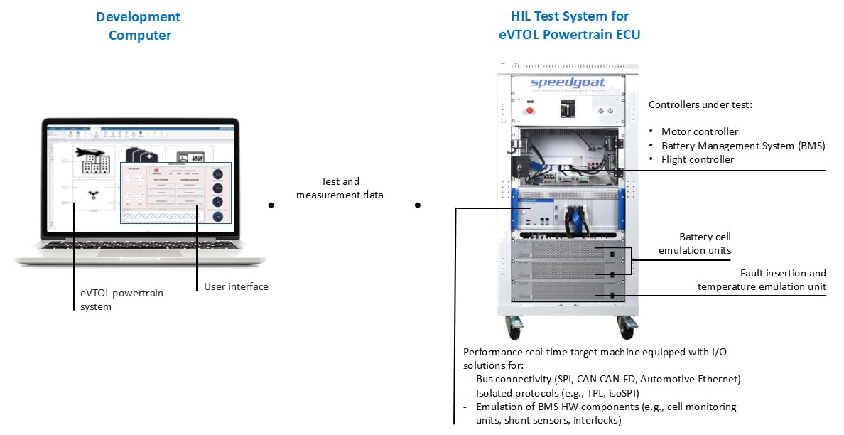
Figure 2: Speedgoat’s eVTOL powertrain HIL test system combines real-time simulation, battery cell emulation and fault insertion to validate motor, battery management and flight controllers under controlled conditions
Within this workflow, requirements can be linked directly to model elements and associated test cases. This creates a traceable relationship between system requirements, control logic, and verification results. When requirements change, the affected models and tests can be identified quickly, enabling engineering teams to maintain consistency across complex development programs.
Real-time HIL testing fits naturally within this model-based workflow. The same system models used during design can be deployed to deterministic real-time simulation platforms, creating a digital twin of the aircraft subsystems that interact with the controller under test. Engineers can then execute test scenarios derived from system requirements and record verification evidence.
Because tests are defined within the development environment, they can also be automated and integrated into continuous integration pipelines. For aircraft certification programs based on standards such as ARP 4754A, DO-178C, and DO-254, this workflow helps maintain traceability between requirements, implementation, and verification activities.
eVTOL Powertrain Controller HIL Testing
Validating eVTOL propulsion systems requires test environments that reproduce the electrical and dynamic behavior of the aircraft powertrain. HIL testing enables production controllers to interact with a real-time digital twin of the aircraft systems. In a demonstration developed by Speedgoat, a battery management controller and motor control unit were connected to a simulated aircraft powertrain environment.
The HIL system integrates these controllers with a real-time simulation of the propulsion and energy storage architecture. The digital twin includes a 400V battery model consisting of 100 cells together with propulsion dynamics representing four electric drives rated at 200kW. Communication takes place over a CAN network, allowing ECUs to exchange signals with the simulated plant as they would in the aircraft.
To support realistic battery validation, the system incorporates cell-level emulation hardware that reproduces voltage and temperature behavior. Selected modules are emulated using dedicated battery cell emulator units, while the remaining cells are modelled within the real-time simulation. The setup includes passive balancing capability, enabling the BMS to apply balancing currents as it would in a physical battery pack. This configuration supports validation of battery monitoring, balancing logic, and protection mechanisms. It also supports fault insertion at the cell level, allowing the controlled introduction of conditions such as short circuits, broken connections, or abnormal voltage behavior in a safe and repeatable manner.
The demonstration then moves from battery-side validation to propulsion control, which introduces a different set of technical requirements, particularly at high switching frequencies. In the demonstration system, the electric drive is simulated using an FPGA-based motor model executing with a 200ns simulation timestep. This model reproduces inverter switching behavior, encoder feedback, and phase-current emulation so that the motor control unit receives realistic electrical signals during testing. PWM signals from the controller are captured at 5ns resolution, allowing switching dynamics and control behavior to be reproduced with signal-level fidelity.
Because the digital twin and controllers operate in closed loop, engineers can test individual subsystems—such as the BMS or motor control unit—while also executing system-level flight scenarios that include propulsion dynamics and battery behavior. Test cases derived from system requirements can be executed automatically using the development environment, enabling automated requirement-based test execution and repeatable regression testing of both individual controllers and their interactions within the wider aircraft powertrain.
HiL at Full Power Levels
While controller HIL testing focuses on validating embedded control behavior, some verification tasks require testing power electronics under realistic electrical loads. Power Hardware-in-the-Loop (PHIL) testing extends the HIL concept by connecting physical power hardware to a real-time simulation of the surrounding system.
The same demonstration architecture can be extended to test a 300kW motor inverter and its control unit under realistic operating conditions.Instead of connecting the inverter to a physical motor, the motor and battery are emulated using high-power amplifiers within an external power testbed. The real-time simulation running on the Speedgoat system exchanges signals with the testbed through a low-latency fiber-optic communication link, ensuring deterministic interaction between the physical inverter and the simulated electrical system.
This configuration can be used to evaluate inverter performance, switching behavior, and control responses at full power levels while maintaining precise control of operating conditions. Because the motor and surrounding system are emulated electrically rather than mechanically, the approach avoids the complexity and safety risks associated with conventional motor test benches.
PHIL testing therefore enables full-power validation of propulsion electronics without exposing aircraft hardware to unnecessary risk while still allowing operating conditions and fault scenarios to be introduced under controlled laboratory conditions.
Certification Alignment
Certification of electrified aircraft systems follows a structured development process that links system requirements to implementation and verification activities. Recent regulatory developments, such as the FAA’s advisory circulars for powered-lift aircraft including eVTOL designs, are helping clarify how these processes apply to new aircraft architectures.
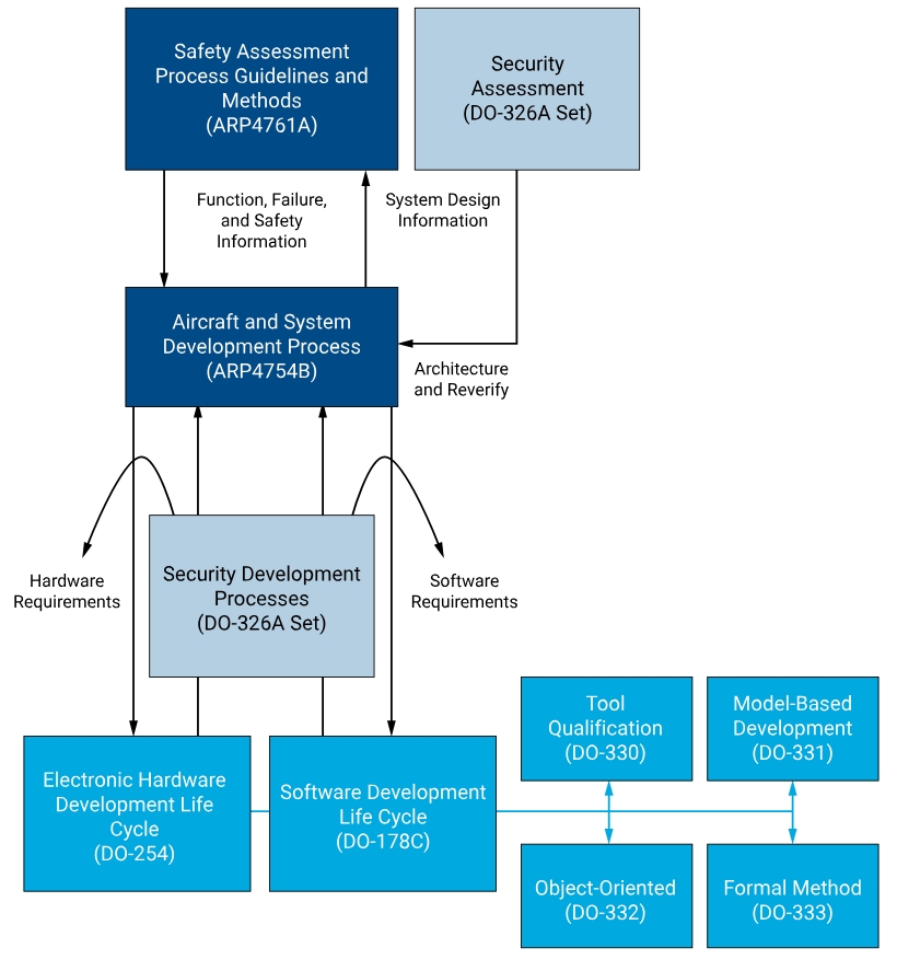
At the aircraft level, development typically follows a top-down approach defined by frameworks such as ARP 4754A, which describes how aircraft functions are allocated to systems and progressively refined into implementable subsystems. Safety assessment processes defined in ARP 4761 complement this workflow by identifying hazards and defining safety requirements that must be addressed during development.
Within this framework, development begins with requirements capture, followed by architectural design and detailed implementation of hardware and software components. In many modern aerospace programs, these activities are increasingly supported by model-based design (Figure 3), where system behavior is first described using executable models. These models allow engineers to analyze system interactions early in the development process and link requirements directly to design elements and test cases.
Click image to enlarge
Supporting standards such as DO-330 (tool qualification) and DO-331 (model-based development supplement) provide additional guidance for programs that rely on automated model-based workflows. When integrated with real-time simulation and HIL testing, these workflows help engineering teams maintain traceability between requirements, implementation, and verification activities, supporting certification efforts throughout the development lifecycle.
Integration
Verification environments must scale from individual controller validation to full aircraft system integration. Hardware-in-the-Loop platforms support these different stages of development, from early component testing through to system-level integration laboratories.
Speedgoat real-time target machines are available in several configurations to support these different phases. Unit and mobile systems provide compact platforms suited to controller development, rapid prototyping, or applications requiring portability. Baseline systems offer expanded I/O capacity for subsystem testing, while performance real-time target machines provide the computational resources and I/O flexibility required for large-scale HIL simulations involving multiple controllers and high-fidelity plant models.
These platforms can be integrated into rack-based test systems that combine real-time simulation hardware with supporting infrastructure such as breakout panels, power supplies, and signal conditioning electronics. This modular architecture allows engineers to interface controllers, sensors, actuators, and communication networks within a single laboratory environment.