Empowering Advanced Motorized Applications with Optimal Current Sensing
The expansion of motorized applications in society demands advanced power-management methodologies to reduce power consumption and optimize functionality.
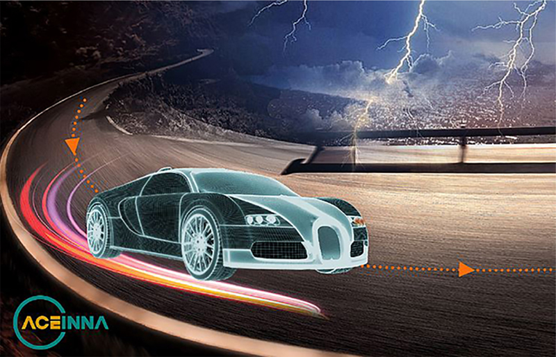
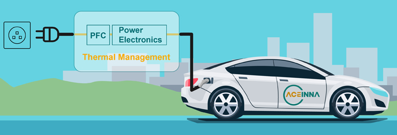
Figure 1. Next generation power sensing technology is essential for tomorrow’s transportation vehicles, related charging infrastructure and industrial motors & equipment
The growth of power and functionality in the latest electronic systems, especially motorized products, has resulted in increasing demands for more efficiency, precision, reliability, and safety. The need for precise power and motion control in these next-generation products put pressure on the electronic design engineer to develop optimized control electronics. These solutions must address the performance needs of the application as well as that of the regulatory environment they will be deployed in, all in a cost-effective manner.
When it comes to the latest electronic systems, the brushless DC motor is a staple in industrial automation, automotive, medical and health care appliances, due to its high reliability and long operational lifetime.
In order to get the most out of these motors, it is important to have properly optimized driver electronics, with fast and precise current sensing to provide the needed performance feedback to determine motor performance. BLDC motors are synchronous devices, in that the stator flux, and therefore the motor phase currents, must be kept synchronous with the rotor position. To run the motor properly, the magnetic flux in the stator must be monitored, which can be done by taking into account the current flow. Current feedback must be fast and precise to accurately control the motor phase current.
If the drive current and the counter-electromotive force (also known as counter EMF, CEMF, back EMF) are not in phase, then the BLDC does not run efficiently, and may even stop. This is another important reason the current in the motor circuit must be monitored. Another approach is to use vector controls, also known as field-oriented control, is another way to monitor the motor. In motor control and robotics, back-EMF usually means using the voltage generated to infer the speed of the motor's rotation. A mathematical technique used to achieve a decoupled control of the flux and torque in a three-phase system. The algorithm is based on tight management of the motor currents, which must be sensed in real time with a high level of accuracy for optimized motor control.
Modern motor-control systems need accurate feedback and signal integrity in order to properly perform the needed levels of system control and stability, correctly managing drive system parameters like speed and torque, while providing system stability. The right solution will make measurements that only target the differential signal, rejecting the common-mode transients caused from PWM cycling, for precise and accurate feedback and control.
No precision without feedback
Current sensors are an important aspect of an optimized motor-control system, and are used to help sense the current, position, and speed of the rotating motor. Recent advancements in AMR sensor technology have significantly improved the accuracy and reliability of current sensing, in a cost-effective manner. The latest solutions integrate the sensor and signal-conditioning circuitry into a single package. In the latest motor control systems, multiple sensors are used in the control loop, and also improve circuit protection by detecting fault conditions that may damage the motor.

Click image to enlarge
Figure 2. High power current sensors are used in many different types of power applications including a wide range of transport and industrial applications as well as in telecom and server farms
The three major ways to measure current in a motor-control system are high side measurements, low side measurements, and inline measurements. Each has its advantages. For example, when a pulse-width modulated (PWM) signal is used to drive the motor, it is hard to obtain accurate measurements due to the common-mode transients (dV/dt). In a three-phase motor, PWM polyphase signals drive the load.
Generally, a brushless motor is more efficient than a brushed one, and this efficiency increase is due to factors like the absence of brushes, as the motor is electrically rather than mechanically commutated. Electrical commutation also leads to positives like an increased product life due to the absence of mechanical wear parts, and their related sparkless operation. However, the more complex the motor, the more sophisticated the control electronics must be to achieve maximum efficiency.
One of the most basic methods uses shunt current sensors, which measure the voltage drop in the motor circuit to determine the current flowing through it. A resistive method that offers good dynamic performance and linearity, using shunt sensors has limitations at both high and low currents. One can use active compensation to overcome these limitations, but at high currents the power dissipation in the shunt itself becomes a growing thermal management issue. In addition, shunt sensors are contact-based, increasing system complexity and circuit failure potential.
When current passes through a wire, a proportionate magnetic field is generated, and AMR sensing exploits this fact of nature for an IC that measures current.
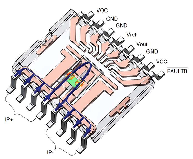
The AMR sensor measures the magnitude of a magnetic field parallel to its sensing direction. The usual way of configuring the sensor so it can measure the magnetic field is to use a U-shaped conductor positioned over the AMR material. The conductor carries the current of interest with magnetic field around it. The AMR sensors sit on top of opposite current carrying conductors with equal distance from a symmetry axis of the sensors. The magnitude of the magnetic field parallel to the sensing direction of the AMR sensor gives the output signal.
Click image to enlarge
Figure 3. The AMR sensor measures the magnitude of a magnetic field parallel to its sensing direction by using a U-shaped conductor positioned over the AMR material
The sensor then converts that magnetic measurement into a voltage. AMR technology uses permalloy, an alloy of nickel and iron whose resistance changes proportionally when presented with a magnetic field. The only contact the sensor has with the motor driver circuit is the magnetic field it is measuring, so just like a transformer, an AMR chip is electrically isolated.
Since anisotropic magnetoresistance (AMR) current-sensing devices like those from ACEINNA are contactless, they provide galvanic isolation with no power dissipation. In addition, they also enable faster readout while correcting offsets via active feedback loops, enabling the circuit to adjust gain parameters and actively compensate for the sensor offset. When used in advanced power systems like a sophisticated motor drive, this integrated sensing solution delivers the needed performance in a significantly smaller footprint over legacy board-level solutions that use shunts or an op-amp and comparator.
Click image to enlarge
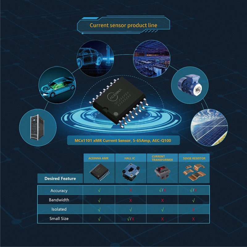
Figure 4. AMR-based current sensing solutions provide a variety of advantages versus other types of current sensing technologies
Circuit protection is critical
Another important role advanced current sensing in motion-control systems addresses is to optimize the circuit protection of the motor drive. In the case of high-performance products, the speeds, power levels, and long operational times of next-generation motorized systems demand the best circuit-protection solutions. In modern systems, traditional “blowing” fuses are inadequate for these advanced driver circuits, as their higher switching speeds and power levels demand real-time monitoring of every critical aspect.
Overcurrent sensing is more than just managing demanding high-power applications like motor drives, it’s also critical to protect the other circuits in the system. Most motion applications have position-sensing and angle sensors, and these subsystems are very susceptible to interference and power irregularities. And for advanced applications, using a fuse for circuit protection doesn’t give you any data on the real-time performance of the power electronics. This prevents engineers from troubleshooting problems for solution creation.
Overcurrent detection response in a motorized system, in fact any powered circuit, can be optimized by using a current sensor. The safety of the overall system is critical, and AMR current-sensing solutions like ACEINNA address overcurrent detection well due to their very fast response and their large current measurement range. Since it is inherently isolated, an AMR current sensor can be used on both the high and low sides of the circuit, improving performance as well as safety in the final design.
Advanced devices like ACEINNA’s current sensors are contactless, offering galvanic isolation, no power dissipation, and faster readout, while correcting offsets via active feedback loops to adjust gain parameters and actively compensate for the sensor offset. Current measurement is a key aspect of over-and undercurrent protection against damage in electronic systems, and intelligent fault management leveraging AMR sensors can also address performance and safety issues like user error and minor damage to cables and connectors.
Smart motor-driver methodologies that leverage monitoring from advanced AMR current sensors protect the circuit and the motors in it against circuit issues, intended or unintended, while optimizing performance. Using ACEINNA AMR current sensors in the high side, for example, can detect ground faults of the phase current (possibly due to wrong wiring, aging etc.), protecting the entire circuit.
Power and heat are inextricably linked in a motorized system, from both electronic and motion inefficiencies. Advanced current sensing enables a circuit to be as efficient as possible, reducing waste heat, and making it easier to also address any external heat the system encounters that can add to the thermal load. Heat generated from the motor driver circuitry can also impact the performance of co-packaged electronics, particularly sensitive analog components, by forcing these products to work at much higher operational temperatures.
Performance advantages
Click image to enlarge
Figure 5. Power factor correction (PFC) improves the power factor ratio and thus the power quality, reducing grid stress, increasing the device’s energy efficiency, while reducing electricity costs
Power quality is a key factor for efficient operation in advanced motorized products, and the system’s power factor is a big part of it. Power factor correction (PFC) improves the power factor ratio and thus the power quality, reducing grid stress, increasing the device’s energy efficiency, while reducing electricity costs. Using advanced current sensing on the low-voltage side of a circuit improves the available power. Form factor is also a consideration, especially in consumer and Mil/Aero applications, so the integrated aspect of ACEINNA’s AMR current sensors reduces parts count and board space required.
Common-mode transients can create overshoot and undershoot phenomena, which can cause feedback issues, including false triggers, ripples in control current, and reductions in overall system efficiency due to things like torque ripple, the periodic change in torque output as the motor rotates. Causes include slight inconsistencies in the individual windings of each phase, so precise construction of the actual motor is a good first step. Other than that, the best way to handle this phenomenon is through a dynamic control system, which demands high accuracy of the measured current to adjust torque accordingly.
An AMR-based solution is not only superior to a shunt in size, it is also more efficient than a shunt-based solution, and generates lower heat than those legacy approaches. In addition, an AMR chip has a wide operating bandwidth, and a higher sampling rate than Hall-based systems at a lower cost. Another advantage to an AMR sensing approach is that it makes an absolute measurement, it does not just track the changes in the circuit. It is also well suited for high-power current-sensing apps like motor control.
Driving forward
In motor control applications, current measurement is fundamental for providing feedback on the motor. Several topologies can be used to develop this current sensing, with pros and cons. AMR-based current-sensing solutions can not only address performance, reliability, and safety. They also help with circuit protection, cost effectiveness, form factor, and other important design issues.