Extending Wireless Charging to Higher Power Applications
New techniques that improve efficiency and distance lay the foundation for cable-free charging of appliances and electric vehicles
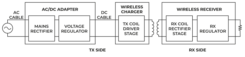
Figure 1: Conventional Wireless Charger Design
While cable-free charging based on standards such as Qi has become commonplace for small, portable devices there have traditionally been challenges in taking wireless up to higher power levels. Now that is set to change with emerging technologies that not only overcome the limitations of conventional wireless standards in terms of power, efficiency, size and cost, but also maintain backward compatibility with those standards.
Wireless Charging - Growth and Challenges
According to the most recent report from industry analysts Research and Markets, the global wireless charger market is predicted to see year-on-year growth of almost 20% between now and 2027. And while much of this will be driven by wireless charging pads and surfaces for smartphones and other portable devices, it is anticipated that higher power applications from kitchen appliances to electric vehicles will also start making more of a contribution. However, satisfying this demand will require innovative new technologies that can deliver increased performance and very high efficiency over greater distances than have been possible with existing wireless charging standards.
Figure 1 shows a block diagram of a conventional inductive charging design that will charge a mobile device based on the Qi standard. In this case an external AC/DC adapter converts the mains voltage to a DC voltage that supplies the wireless charger transmitter coil section through an external DC cable. The coil then transfers the energy to the wireless receiver built into the device to be charged. In such a design the typical maximum charging distance is around 5 mm and the maximum power is around 30 W.
From a system perspective it takes at least three different blocks comprising five distinct stages in cascade to realize this design:
1. A mains rectifier to rectify the input line voltage. For low-power applications this may simply be a diode bridge and in more complex designs a power factor corrected (PFC) stage.
2. A transmitter voltage regulator (typically a buck converter with two active elements and one high-current magnetic element) to manage the power to be transmitted.
3. A DC/AC transmitter coil driver stage to energize the coil. This resonant stage may be half-bridge with two active elements or a full bridge with four active elements. In both cases operation sees a load-dependent efficiency curve that achieves ZVS (Zero Voltage Switching) only in full-load conditions, with a degradation of efficiency for lighter loads or when the coupling between receiver and transmitter is far from nominal conditions.
4. A wireless receiver AC//DC coil full bridge rectifier stage to rectify the voltage at the receiver coil.
A DC/DC receiver voltage regulator (again, typically for high-power applications a buck converter with two active elements and one magnetic element) to regulate the output voltage.
As a result a traditional wireless charging system has between 12 and 16 active devices, at least two magnetic components, two coils, an AC cable and a DC cable. This number of elements not only contributes to a high bill of material (BoM) cost but also impacts on overall system efficiency.
E2WATT Wireless Charging
It was with these challenges in mind that Eggtronic has developed E2WATT – a hybrid AC power solution that is both a power supply and a wireless charger. Based on a proprietary inductive technology, E2WATT facilitates higher power densities and larger distances than previous wireless charging designs and supports efficiency levels comparable with the best conventional AC wired adapters. E2WATT lays the foundation for taking wireless charging from a few watts to tens of kilowatts.
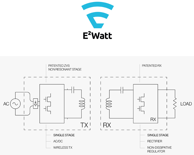
Figure 2 shows how E2WATT is based on reducing to just two the total number of stages required to implement a complete, end-to-end wireless charging system. This is achieved thanks to a topology that merges multiple stages into a multi-functional, single-stage ZVS-ZCS (zero voltage switching, zero current switching) wireless power supply.
As Figure 2 illustrates, the two stages of an E2WATT wireless charging system are:
1. A transmitter (AC/AC) stage supplied directly from the mains. This stage is modelled as a bridgeless AC converter that is able to drive the coil using an innovative, proprietary half-bridge architecture based on two Navitas gallium nitride (GaN) power ICs and two diodes. A design that allows fine control of energy transmitted through the coils guarantees both good voltage regulation and, if necessary, supports power factor control.
2. A single-stage AC/DC receiver half-bridge that requires just two active devices and acts simultaneously as secondary side rectifier and non-dissipative output regulator.
Click image to enlarge
Figure 2: Eggtronic E2WATT Wireless Charging Block Diagram
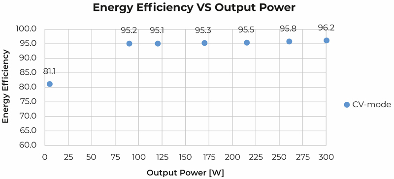
In the transmitter stage, thanks to a combination of ZVS and near-ZCS conditions and robustness to input and load variations, the switching power losses are close to zero. And because the transmitter stage is not resonant, ZVS operation can be reached for any load condition. As a result, transmitter efficiency remains high over a wide range of output powers (see Figure 3).
Click image to enlarge
Figure 3: E2WATT Transmitter Stage Efficiency vs Output Power
The single-stage receiver commutes always in ZVS conditions and incorporates patent-pending techniques including a low-latency data exchange scheme that have allowed Eggtronic to reduce receiver temperatures when compared to conventional designs by as much as 30°C at 30 W. By controlling the ratio between the active power delivered to the load and the reactive power reflected to the primary, the receiver stage provides a fast control loop that enables output voltages to be finely regulated without the need for additional buck converters or LDOs in series.
Eggtronic’s proprietary architecture also incorporates a second control loop that that further improves efficiency by minimizing the reactive power across the whole transmitter and receiver system. As well as the GaN ICs from Navitas Semiconductor, Eggtronic is also using a Microchip Technology dsPIC33 microcontroller to enable the unique system architecture that results in increased z-distance charging.
Benefits of E2WATT Technology
By developing proprietary, single-stage ZVS circuits that directly provide low-loss conversion of AC mains to an excitation voltage for a wireless transmitter Eggtronic has created a completely new approach to wireless charging design based on just six active devices (including two primary side diodes), no extra magnetics, two coils a single AC cable. This new approach delivers two fundamental benefits. Firstly, the bill of materials in terms of active and passive components is reduced by as much as 50% compared to conventional designs. And, secondly, efficiency levels are increased from around 70% to 96%. The latter is particularly significant because it means that E2WATT has the potential to replace both wireless and wired charging schemes.
While offering Qi compatibility to ensure it can be used to charge existing devices, the first iterations of E2WATT are already reaching eight times further than conventional Qi-based designs and are delivering powers of up to 300 W. This greatly expands the current scope of wireless power technology and opens up new opportunities for charging smartphones, laptops, TVs, and other consumer devices as well as the wireless powering of home appliances and electric vehicles.
Eggtronic


