Author:
Robert Green, Keithley Instruments, a Tektronix Company
Date
03/23/2015
 PDF
PDF
It has been predicted that, within a decade, the Internet of Things (IoT) will grow to encompass billions or even trillions of wireless devices and sensors. However, that growth will depend to some degree on the ability of their manufacturers to drive down the cost of each of these devices. At the same time, however, these devices must be thoroughly characterized during their design and development, and then tested quickly, accurately, and cost-effectively during production.
To operate reliably for extended periods on a finite amount of battery power, these tiny wireless devices must consume power sparingly. This requires characterizing a device’s power consumption in all of its operating states so developers can understand where to focus their efforts.
Characterizing the power consumption of these devices demands instrumentation capable of making both sensitive measurements and high-speed measurement. For example, when characterizing load currents, the test system must be capable of measuring low currents, sometimes down to tens of microamps or less, when the device is in its sleep and standby modes.
Too many cycles
To produce stable and accurate measurements of these low-level currents, test systems are generally configured to make many measurements over a long measurement interval in order to average out electrical noise created in the device and noise from the external environment. Filtering can also be used to ensure quality measurements.
However, a measurement period that extends over a number of AC power line cycles along with filtering can result in a measurement time well into the seconds and often tens of seconds. This extended measurement period runs in opposition to the need for high speed to increase throughput and reduce the cost of test for each part.
In addition to making slow, sensitive measurements of the sleep or standby currents of IoT devices, the instrumentation must make very fast current measurements when an IoT device is active, such as when it is transmitting data.
The challenge is to capture and measure a load current pulse that might last for only a few hundred microseconds. The instrumentation must respond quickly to make a measurement in this very short time interval. In this situation, the test system designer must trade off some measurement accuracy and resolution to get speed.
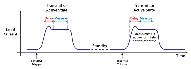
Figure 1 illustrates a typical load current profile for a wireless IoT device. In sleep mode, the current is very low, but when the device is transmitting, the load current rises dramatically for a short period. To measure this current, the test instrumentation must respond to control signals that indicate when the device is transitioning into the active state so that the instrumentation can initiate the high-speed measurement. The instrument should also allow flexibility in selecting a measurement time so that the best measurement can be acquired.
Click image to enlarge
Figure 1. The load current profile for a typical wireless device includes long periods of low current consumption with short bursts of high current consumption when the device is stimulating or transmitting data.
Multitasking test
Because the requirements for making accurate low current measurements during sleep and standby modes and those for making very fast high current measurements during the active mode are so different, one might assume that multiple instruments would be required to make these measurements. For example, it would be possible to put a sense resistor in series with the test lead that connects a power supply to the device-under-test and measure the voltage across the sense resistor with a digital multimeter (DMM).
The problem is that it would be very challenging to choose the appropriate value for the sense resistor. A small resistor value adds only a small additional error to the load current measurement, but if the value is too small, the DMM might lack sufficient sensitivity to measure the low sleep mode current, or even the standby mode current, accurately.
Although an oscilloscope is well suited to the task of capturing the magnitude of short, active-mode load current pulses, DMMs offer much greater precision when making voltage measurements. A power source, a DMM, and an oscilloscope might be required to make all the necessary measurements.
A source measure unit (SMU) instrument could be another possible option for this application. They can measure very low currents (down to picoamps or less) accurately; unfortunately, they are not typically designed to capture narrow pulses. Also, SMUs are generally low power instruments and so might not have sufficient total power to deliver the peak current necessary to characterize a device that draws a large amount of peak power. In addition, because of their extraordinary sensitivity, SMU instruments can be relatively expensive solutions for testing low-cost parts.
A single-instrument solution
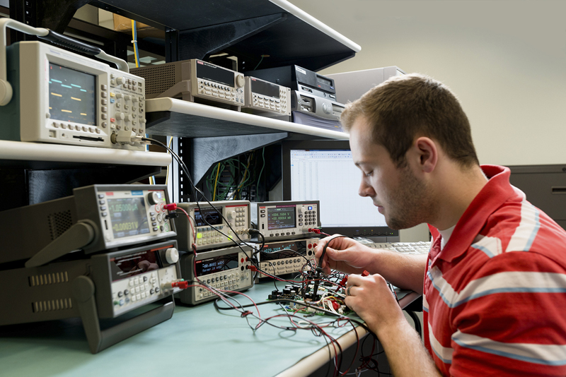
Obviously, most design and test engineers would prefer a solution that’s less complicated to implement than configuring a test setup with a DC power supply to provide the source voltage, a sense resistor, a DMM, an oscilloscope, an SMU instrument, and a switching system to tie them all together. If they can make the measurements they need with only a single instrument, testing can begin sooner because there is less equipment to set up (see Figure 2). Automating the measurement is simpler as well with only one instrument to program. This eliminates the need to synchronize multiple instruments and allows the engineer to focus on making the measurement.
Click image to enlarge
Figure 2. Benchtop characterization of low-power wireless devices demands instrumentation that combines the sensitivity necessary to measure quiescent currents with the speed to capture narrow current pulses, as well as a wide current sourcing range.
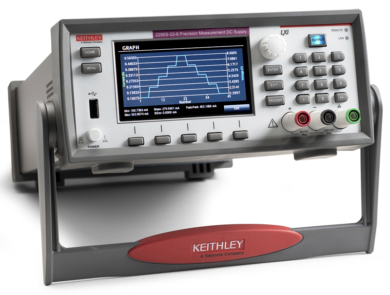
Instrument designers are only beginning to take on the challenge of creating instruments capable of providing the level of power needed to energize a wireless IoT device without sacrificing the ability to measure both very low load currents and much higher active load currents accurately and with high resolution. Such instruments are only now entering the market in the form of power supplies with integrated precision measurement capabilities (see Figure 3).
Click image to enlarge
Figure 3. Keithley’s Series 2280S Power Supplies can characterize small load currents with 10nA resolution and measure up to 6A very accurately. Four load current measurement ranges—10A, 1A, 100mA, and 10mA—allow measuring both full load currents and standby/sleep mode currents with 6 1/2 digit resolution. It can also capture dynamic load currents as short as 140μs.
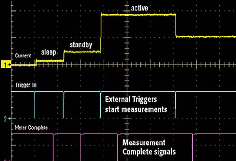
In order to measure very low standby or sleep mode currents accurately, a power supply/measurement instrument must be capable of DMM-quality measurements with up to 6½ digits of resolution. When making high current measurements, it has to capture current pulses as short as hundreds of microseconds. Also, because some devices, such as implantable medical sensors or other portable, battery-powered devices, have a power-up load sequence and a power-down sequence, similar to the one shown in Figure 4, the instrument chosen must have the triggering capabilities needed to make multiple, synchronized measurements at each state of the power-up or power-down cycle.
Click image to enlarge
Figure 4. As a device is powered up during characterization or production testing, the load current increases as it cycles through the sleep, standby, and active modes. To characterize this start-up sequence, the test setup must be capable of making fast measurements synchronized to the device’s state changes.
For instruments intended for use in an automated test system in addition to the designer's bench, it’s essential that it offer the LAN, USB, or GPIB interfaces and digital inputs and outputs needed to integrate it with other test equipment in a rack. To simplify characterization on the benchtop, consider a power supply with advanced display capabilities, including built-in graphing functions that simplify monitoring the stability of the load current, capturing and displaying a dynamic load current, or viewing a start-up or turn-off load current.