Flyback Controller Incorporates Active PFC into a Single Stage Converter
Power systems operating from the AC mains has an associated power factor
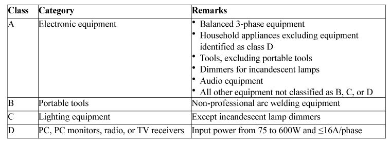
Table 1. IEC 61000-3-2 Classifications
Any power system operating from the AC mains has an associated power factor defined as the way it draws current from the source. The power factor of an AC electric power system is defined as the ratio of the real power flowing to the load to the apparent power and is a dimensionless number between 0 and 1. Real power is the capacity of the circuit for performing work in a particular time. Apparent power is the product of the current and voltage of the circuit. Due to a non-linear load that distorts the wave shape of the current drawn from the source, the apparent power will be greater than the real power. In an electric power system a load with a low power factor draws more current than a load with a high power factor for the same amount of useful power transferred. These higher currents increase the energy lost in the distribution system and require larger wires and other equipment for transmission. Because of the costs of larger equipment and wasted energy, electrical utilities charge a higher price where there is a low power factor. Furthermore, a power supply's power factor affects the harmonics that an AC-DC supply generates on the AC mains, and so electric utilities have major difficulties distributing power for loads that include AC-DC power supplies without power factor correction. These power supplies are nonlinear loads which:
- Distort the AC waveform.
- Cause harmonics currents that can impact operation of other equipment on the same utility line.
- Can cause fires from neutral wires overheating.
- Can overstress and shorten the lives of power transformers.
- Can overload AC-power generators.
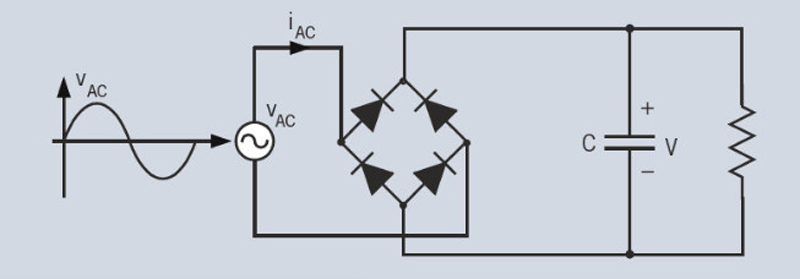
A typical off-line power supply loads the AC mains power line with a diode bridge driving a capacitive load as shown in Figure 1. This load is nonlinear due to it primarily charging a capacitor and this type of load draws line current only during the peak of the sinusoidal line voltage, resulting in line current input peaks that cause power line harmonics. Power Factor Correction (PFC) One way to improve the power factor is to use a filter. This is commonly referred to as passive PFC. It is possible to design a filter that passes current only at line frequency (e.g. 50 or 60 Hz). This type of filter is normally used for low power requirements and reduces the harmonic current, which means that the non-linear device now looks like a linear load and the power factor can be brought to near unity, using capacitors or inductors as needed. However, this type of filter requires large-value high-current inductors, which are both bulky and expensive.
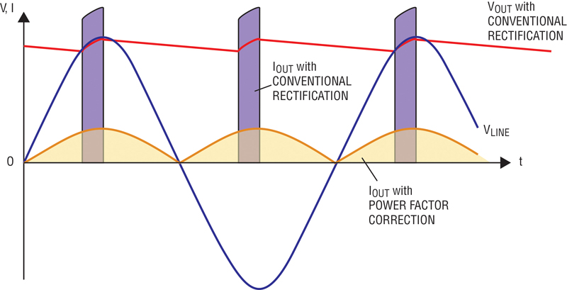
Active PFC Active PFC is a power electronic system that controls the amount of imaginary power drawn by a load in order to obtain a power factor as close to unity as possible. In most applications, active PFC controls the input current of the load so that the current waveform is proportional to the mains voltage waveform (a sine wave). Active PFC normally consist an extra switching boost converter power stage that requires a control IC, switching MOSFET and power inductor. Active PFC puts the voltage and current nearly in phase and the reactive power consumption approaches zero. This enables the most efficient delivery of electrical power from the power company to the user. Figure 2 shows what the current to an off-line switching power supply looks like without PFC and what it looks like with active a PFC of 1.0.
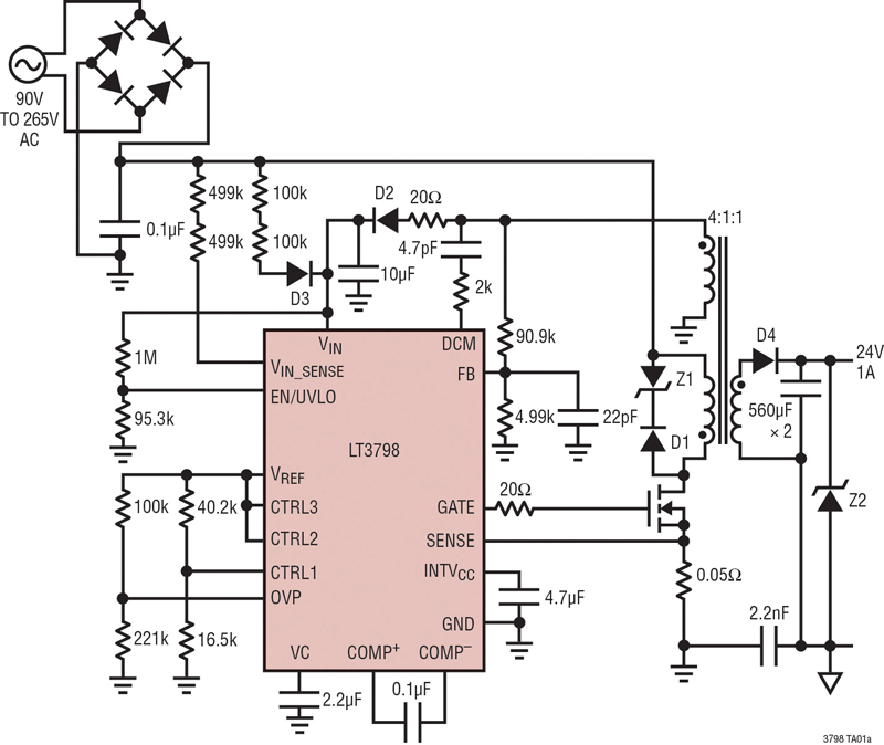
Up until now power supply designs have required the used of an addition power stage to incorporate PFC. Whether it's active or passive PFC, additional components have been required which increases the cost, circuit size and complexity. However, Linear Technology recently announced a revolutionary isolated flyback controller that combines active PFC into a single stage converter without the need for additional components. Introduction The LT3798 is a constant current/constant voltage isolated no-opto required flyback controller with single stage active PFC. A power factor of greater than 0.97 can be achieved by actively modulating the input current, eliminating the need for an extra switching power stage and associated components. In addition, no optocoupler or signal transformer is required for feedback since the output voltage is sensed from the primary-side flyback signal. A LT3798-based design easily complies with most Harmonic Current Emissions specification. Efficiencies greater than 86% can be achieved with output power levels up to 100W. The device's input voltage range is dependent on the choice of external components and it can operate over a 90VAC to 307VAC input voltage range and can be easily scaled to higher or lower input voltages. Furthermore, the LT3798 can be designed into high input voltage DC applications, making it well suited for industrial, EV/EHV automotive, mining, and medical applications. The LT3798 utilizes critical condition mode operation enabling the use of a smaller transformer compared to continuous conduction mode designs, further reducing the solution size. The LT3798 is comes in a thermally enhanced 16-pin MSOP package. Figure 3 shows a typical application circuit for the LT3798 which converts a 90 to 265VAC input voltage to 24V @ 1A output. This IC is a current mode switching controller that is specifically intended for generating a constant current/constant voltage supply with an isolated flyback topology. To maintain output voltage regulation this design senses the output voltage from the second primary-side transformer winding. The LT3798 eliminates the need for an optocoupler, opto driver and secondary-side reference voltage, all while maintaining isolation between primary and secondary with only one part having to cross the isolation barrier. It also employs a primary-side sensing scheme that is capable of detecting the output voltage through the flyback primary-side transformer winding. During the switch off-period, the output diode delivers the current to the output, and the output voltage is reflected to the primary-side of the flyback transformer. The magnitude of this reflected voltage is the summation of the input voltage and output voltage, which the LT3798 is able to reconstruct. During a typical cycle, the gate driver turns on the external MOSFET so that a current flows in the primary winding. This current increases at a rate proportional to the input voltage and inversely proportional to the transformer's magnetizing inductance. The control loop determines the maximum current and a comparator turns off the switch when it reaches that current. When the switch turns off, the energy in the transformer flows out the secondary winding through the output diode, D4 (refer to Figure 3). LT3798 Power Factor Correction The LT3798's VIN_SENSE pin connects to a resistor divider from the supply voltage. The lower of the two error amplifier outputs is multiplied with the VIN_SENSE pin voltage. If the LT3798 is configured with a fast control loop, slower changes from the VIN_SENSE pin would not interfere with the current limit or the output current. The COMP+ pin would adjust to the changes of the VIN_SENSE. The only way for the multiplier to function is to set the control loop to be an order of magnitude slower than the fundamental frequency of the VIN_SENSE signal. Operating offline, the fundamental frequency of the supply voltage is 120Hz so the control loop unity gain frequency needs to be set less than approximately 12Hz. Without a large amount of energy storage on the secondary side, the output current will be affected by the supply voltage changes, but the DC component of the output current will be accurate. An internal multiplier enables the LT3798 to achieve high power factor and low harmonic content by making the peak current of the main power switch proportional to the line voltage. A LT3798 design enables a power factor greater than 0.97 for most applications and will comply with most Harmonic Emission requirements. Transformer Design Considerations The transformer specification and design is a critical part of successfully applying the LT3798. In addition to the usual list of caveats dealing with high frequency isolated power supply transformer design such as low leakage inductance the following information should be carefully considered. Since the current on the secondary side of the transformer is inferred by the current sampled on the primary, the transformer turns ratio must be tightly controlled to ensure a consistent output current. A tolerance of �5% in turns ratio from transformer to transformer could result in a variation of more than �5% in output regulation. Fortunately, most magnetic component manufacturers are capable of guaranteeing a turn's ratio tolerance of 1% or better. Linear Technology has worked with several leading magnetic component manufacturers to produce predesigned flyback transformers for use with the LT3798 and this list of transformers are shown in the LT3798 data sheet. Conclusion The significance of power factor lies in the fact that utility companies supply customers with volt-amperes, but bill them for watts. Power factors below 1.0 require these companies to generate more than the minimum volt-amperes necessary to supply the real power (watts) which increases generation and transmission costs that are passed on to the consumer. The LT3798 is a unique revolutionary new part for its ability to provide off-line isolated power conversion with active PFC in single stage flyback converter and is done without the need for an optocoupler to sense the output voltage. This combination significantly simplifies the design, reduces the line voltage harmonic distortion and solution size, improves the power factor and reduces the cost of the converter that can be used for a wide variety of off-line and high DC-input applications. www.linear.com
Up until now power supply designs have required the used of an addition power stage to incorporate PFC. Whether it's active or passive PFC, additional components have been required which increases the cost, circuit size and complexity. However, Linear Technology recently announced a revolutionary isolated flyback controller that combines active PFC into a single stage converter without the need for additional components. Introduction The LT3798 is a constant current/constant voltage isolated no-opto required flyback controller with single stage active PFC. A power factor of greater than 0.97 can be achieved by actively modulating the input current, eliminating the need for an extra switching power stage and associated components. In addition, no optocoupler or signal transformer is required for feedback since the output voltage is sensed from the primary-side flyback signal. A LT3798-based design easily complies with most Harmonic Current Emissions specification. Efficiencies greater than 86% can be achieved with output power levels up to 100W. The device's input voltage range is dependent on the choice of external components and it can operate over a 90VAC to 307VAC input voltage range and can be easily scaled to higher or lower input voltages. Furthermore, the LT3798 can be designed into high input voltage DC applications, making it well suited for industrial, EV/EHV automotive, mining, and medical applications. The LT3798 utilizes critical condition mode operation enabling the use of a smaller transformer compared to continuous conduction mode designs, further reducing the solution size. The LT3798 is comes in a thermally enhanced 16-pin MSOP package. Figure 3 shows a typical application circuit for the LT3798 which converts a 90 to 265VAC input voltage to 24V @ 1A output. This IC is a current mode switching controller that is specifically intended for generating a constant current/constant voltage supply with an isolated flyback topology. To maintain output voltage regulation this design senses the output voltage from the second primary-side transformer winding. The LT3798 eliminates the need for an optocoupler, opto driver and secondary-side reference voltage, all while maintaining isolation between primary and secondary with only one part having to cross the isolation barrier. It also employs a primary-side sensing scheme that is capable of detecting the output voltage through the flyback primary-side transformer winding. During the switch off-period, the output diode delivers the current to the output, and the output voltage is reflected to the primary-side of the flyback transformer. The magnitude of this reflected voltage is the summation of the input voltage and output voltage, which the LT3798 is able to reconstruct. During a typical cycle, the gate driver turns on the external MOSFET so that a current flows in the primary winding. This current increases at a rate proportional to the input voltage and inversely proportional to the transformer's magnetizing inductance. The control loop determines the maximum current and a comparator turns off the switch when it reaches that current. When the switch turns off, the energy in the transformer flows out the secondary winding through the output diode, D4 (refer to Figure 3). LT3798 Power Factor Correction The LT3798's VIN_SENSE pin connects to a resistor divider from the supply voltage. The lower of the two error amplifier outputs is multiplied with the VIN_SENSE pin voltage. If the LT3798 is configured with a fast control loop, slower changes from the VIN_SENSE pin would not interfere with the current limit or the output current. The COMP+ pin would adjust to the changes of the VIN_SENSE. The only way for the multiplier to function is to set the control loop to be an order of magnitude slower than the fundamental frequency of the VIN_SENSE signal. Operating offline, the fundamental frequency of the supply voltage is 120Hz so the control loop unity gain frequency needs to be set less than approximately 12Hz. Without a large amount of energy storage on the secondary side, the output current will be affected by the supply voltage changes, but the DC component of the output current will be accurate. An internal multiplier enables the LT3798 to achieve high power factor and low harmonic content by making the peak current of the main power switch proportional to the line voltage. A LT3798 design enables a power factor greater than 0.97 for most applications and will comply with most Harmonic Emission requirements. Transformer Design Considerations The transformer specification and design is a critical part of successfully applying the LT3798. In addition to the usual list of caveats dealing with high frequency isolated power supply transformer design such as low leakage inductance the following information should be carefully considered. Since the current on the secondary side of the transformer is inferred by the current sampled on the primary, the transformer turns ratio must be tightly controlled to ensure a consistent output current. A tolerance of �5% in turns ratio from transformer to transformer could result in a variation of more than �5% in output regulation. Fortunately, most magnetic component manufacturers are capable of guaranteeing a turn's ratio tolerance of 1% or better. Linear Technology has worked with several leading magnetic component manufacturers to produce predesigned flyback transformers for use with the LT3798 and this list of transformers are shown in the LT3798 data sheet. Conclusion The significance of power factor lies in the fact that utility companies supply customers with volt-amperes, but bill them for watts. Power factors below 1.0 require these companies to generate more than the minimum volt-amperes necessary to supply the real power (watts) which increases generation and transmission costs that are passed on to the consumer. The LT3798 is a unique revolutionary new part for its ability to provide off-line isolated power conversion with active PFC in single stage flyback converter and is done without the need for an optocoupler to sense the output voltage. This combination significantly simplifies the design, reduces the line voltage harmonic distortion and solution size, improves the power factor and reduces the cost of the converter that can be used for a wide variety of off-line and high DC-input applications. www.linear.com


