How to Deliver for Low-Power LiDAR and Rangefinders
Power-efficient solutions for precision sensing
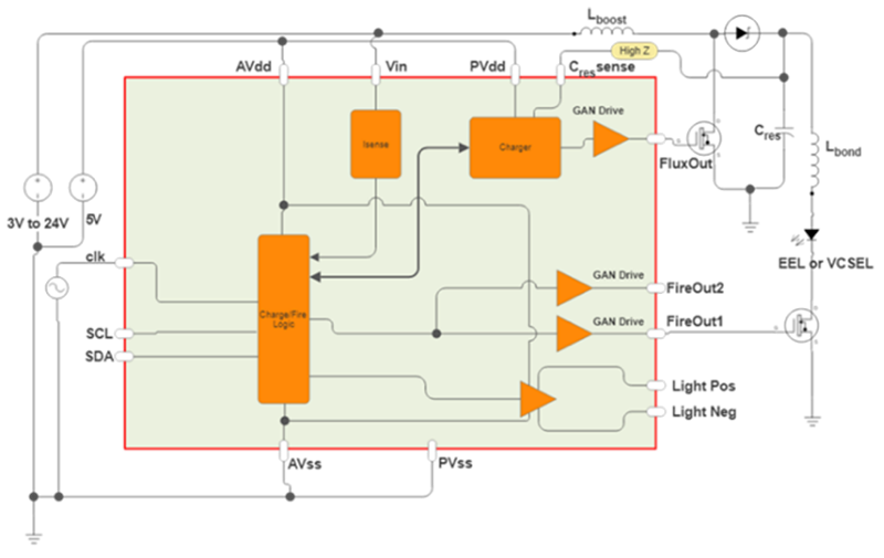
Figure 1: A resonant circuit for short-pulse laser firing
Time-of-flight (ToF) laser sensors provide accurate range and depth measurements that are invaluable for a host of applications: from LiDAR systems in cars and delivery drones to rangefinders for construction, surveying, sports computers and hunting sights.
These technologies enable not only distance measurements, but also (for ADAS and autonomous vehicles) give an enhanced level of resilience over camera-based systems, which are negatively affected in low light conditions, by glare, and by rain and fog. As Brett Schreiber, an attorney specializing in AV crashes, put it “Everyone who has been following collision-avoidant technology since the 1990s knows that the holy trinity is radar, LiDAR and cameras.” As such, LiDAR’s implementation will be vital as robotaxis shift from the Phoenix, San Francisco and the Sun Belt to cities like Minneapolis, New York, Seattle or Anchorage where the weather conditions can be far from ideal.
But LiDAR and ToF lasers are not without their issues. Notably, they are a high-cost, high-power technology, and (with SWaP-C criteria affecting virtually every component selection within a car) this is significantly limiting their use. Tesla, for example, has said it will remain LiDAR free. And Waymo reduced the number of LiDAR sensors to 4 down from 5 in its latest 6th generation vehicle, as reported by Automotive World. It’s certainly true that vision-based alternatives that analyze 2D video images with neural networks can potentially offer lower cost and lower power under favorable environmental conditions.
It doesn’t need to be this way though, and recent advances have shown it is possible to eliminate many of the inefficiencies that place excessive demands on the power budget and requires significant BOM cost for thermal management.
Inefficiencies
The main power demand in a LiDAR module comes from the transmitter circuitry containing the laser diode and driver that generate pulsed emissions in the visible or near-infrared spectrum. Here, 50% energy is lost in the isolation circuitry due to the resistive charging between multiple capacitors (Fig.2), and then an additional 50% to 80% energy is lost in the optical conversion – meaning the end-to-end electrical-to-optical conversion efficiency of even the most efficient laser diodes will typically be little more than 20%.
At 85 mph, the stopping distance of a well-maintained car in dry conditions is over 120 m (390’) plus thinking time, in the wet this increases to nearly 200 m (650’). For LiDAR to measure such distances, the peak optical power required will between 70 W and 200 W for 905 nm lasers, meaning the supplied driving power needs be around 1 kW.
To ensure adequate resolution, particularly for objects at close distances, while also working within maximum permissible exposure guidelines for eye safety, the driving circuit needs to generate pulses in the region of 5 ns. This means the laser driver must switch a high current at extremely high speed, however the stray inductances within circuit connections, board traces, and package bondwires act against such rapid current change and can prevent achieving the required pulse width.
To engineer a solution to this, designers have added a capacitor circuit that combines with the effect of the stray inductance to create resonance (figure 1). This makes it possible to create a driver capable of generating a suitably short pulse, determined by the L, C combination.
To achieve the desired pulse duration of a few nanoseconds, the resonant capacitance, Csupply, must be very small and in practice, the combined value of the stray inductances in the circuit (Lbond in figure 1) is about 1 nH.
As such, Csupply can be only a few nanofarads for resonance to occur and, using such a small value of capacitance, the voltage applied to Csupply must be in the order of 100 V for the laser to deliver the required peak optical power. This therefore requires the addition of a boost regulator in the circuit to increase the supply voltage: up from 12 V for automotive batteries; and up from just 3-5 V for lithium-batteries in handheld rangefinders.
Resonant Driver Circuit
Figure 2 shows how a typical resonant laser-diode driver is implemented using discrete components. In this, the Boost Voltage Regulator (Boost VR) provides the high voltage needed at Csupply to operate the resonant circuit when transferring energy into the laser. Additionally, a separate gate driver and FET are needed for the Boost VR, as is isolation between Cfilter and Csupply.
Click image to enlarge
Figure 2: Resonant gate driver and boost regulator
In addition to calculating the component values and operating voltage for the resonant circuit, achieving the high speeds and slew rates also depends on proper consideration of circuit layout and component selection. For fast switching at high voltage, a GaN transistor is often used in preference to an ordinary silicon MOSFET. A GaN driver is therefore required, and this in turn can add further challenges, such as optimizing design of the gate loop and ensuring suitable driver turn-on/turn-off timing.
In addition, the driver circuit ground connections must be designed carefully to prevent voltage overshoots and ground bounce from disrupting proper transistor switching and potentially damaging the transistor.
However, careful design cannot overcome deeper issues with this circuit when implemented with discrete components, which is highly inefficient – as we highlighted earlier, no more than 50% of the energy in the Cfilter side is transferred to Csupply; and this is before the inherent inefficiency of the laser itself. This being the case, operating at high power produces high losses that can impose heavy demands on the power supply and the associated self-heating can require large heatsinks that prevent achieving a compact overall design. System self-monitoring and fault detection must also be implemented, as well as fast-shutdown circuitry to protect eye safety.
Discrete Versus Integrated Circuits
Integrating the boost stage, isolation, gate driver, control logic, and safety functionality in a single firing-control IC simplifies the LiDAR laser driving circuit and can achieve higher efficiency as well as a smaller form factor.
Figure 3 shows how such an IC can greatly reduce the number of external components, enabling a smaller footprint and lower bill-of-materials. From this, we can see that the external boost regulator is not required, and all gate-driving circuitry can be optimized and integrated on-chip. External component requirements are therefore simplified to just the GaN transistor and laser, either an edge-emitting laser (EEL) or vertical-cavity surface-emitting laser (VCSEL), as well as the resonant circuit that comprises a single capacitor with a boost inductor, MOSFET, and Zener diode. And because the resonant circuit contains only a single capacitor, no isolation is required.
So, while the inefficiencies of the laser itself still exist, this approach eliminates the 50% energy losses that were incurred in the discrete capacitor-to-capacitor charging circuitry while still ensuring a short and tightly controlled pulse duration. The fault detection and shutdown circuitry implemented on chip alongside the timing and control features can achieve nanosecond response times, exceeding mandatory safety requirements. Moreover, the chip’s I2C connection simplifies setting up and adjusting the laser power-control parameters through the host system.
Click image to enlarge
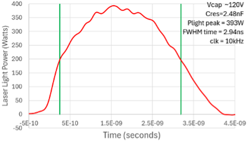
Figure 3: Silanna’s Firepower integrates laser control, driving, and safety circuitry in a single chip (3a) with laboratory test results on Firepower (3b)
Laboratory testing has demonstrated a single-chip laser driver operating from a low-voltage supply in the range 3 V-24 V, which generates 120 V on the resonant charging circuit and controls the GaN laser-firing transistor. The circuit produces an ultra-short optical pulse of 3 ns duration and 400 W output power, as shown in figure 3b.
This highlights that, for depth-of-field and ranging measurements, the benefits of ToF lasers can be brought into LiDAR arrays and simpler rangefinder applications without the complexity, without the BOM and without accepting excessive inefficiencies.
Indeed, leveraging resonance to reduce power consumption, and semiconductor integration to reduce BOM, permits compact, economical, and power efficient LiDAR laser firing circuitry. This means automotive sensor fusion and portable battery-powered ranging systems can then take full advantage of its robustness and direct-measurement accuracy to deliver the best possible performance in all conditions.