How to easily carry out DC/DC converter testing using a DC power analyzer and oscilloscope
The power system technologies of modern electronic equipment are facing extreme challenges due to the need for an increase in the power efficiency of the systems, especially devices powered by a battery. The main system block involved in power conversion and delivery is the DC-DC converter, which converts DC power from an unregulated to a regulated voltage. Many designers want to verify or characterize the performance of the DC-DC converter in terms of efficiency, load and line regulation, power supply rejection ratio (PSRR) analysis, transient response, ripple, and turn-on time.
Testing DC/DC converters in a bench top environment to carry out the measurement described above, requires different test instruments such as digital multimeters (DMM), oscilloscope, power supply and electronics load. The main challenge to carry out these measurements is to synchronize the instruments to execute various measurements.
Using a DC Power Analyzer and Software for DC/DC Converter Parameter Testing
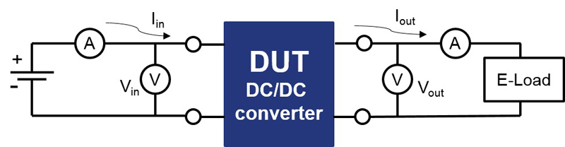
The test setup will depend upon the type of test being performed. To characterize the converter, you must connect it between the power source and the electronic load to sink the current from the converter (Figure 1). Obviously, it’s necessary to measure the voltage and current as input (Vin and Iin respectively) and the voltage and current across the output (Vout and Iout respectively). These couples of values are the input power (Pin) and the output power (Pout).
The DC characterization can be simplified by replacing the power supply, multimeters and electronic load with an integrated DC Power Analyzer. To help the designer overcome these tests, a DC power analyzer should combine one to four programmable DC power and measurement units (2 or 4 quadrant source and measurement unit, aka SMU), a DMM for each channel, an oscilloscope (that can show voltage, current and power versus time, this feature allows the designer to view the signal in real time), and a data logger in one integrated package.
Each of the four output characteristics are determined by which plug-in power module is used for that output. Some DC power analyzers may have 34 different power modules available to ensure a good match for a wide DC/DC validation with different power values. A way to build a simple test flow on DC/DC converter with a DC power analyzer without programming hassles, is through software. This makes it easy to connect the instruments and quickly capture and view the data from the instruments. If you select software with an intuitive user interface, it is easy to connect and synchronize different instruments to run the custom validation test.
Efficiency Test
Typically, the most important DC test for the DC-DC converter is efficiency. This is especially true for battery-powered devices, because efficiency has a direct impact on the life of a device.
The efficiency of the converter is the ratio between the output power and the input power. To run the test, use one channel of the DC power analyzer as input voltage and monitor the converter input current. Use another channel, configured as a load by setting it to sink current, and measure the voltage on the output of the converter. Software can be utilized to draw the flow of the test.
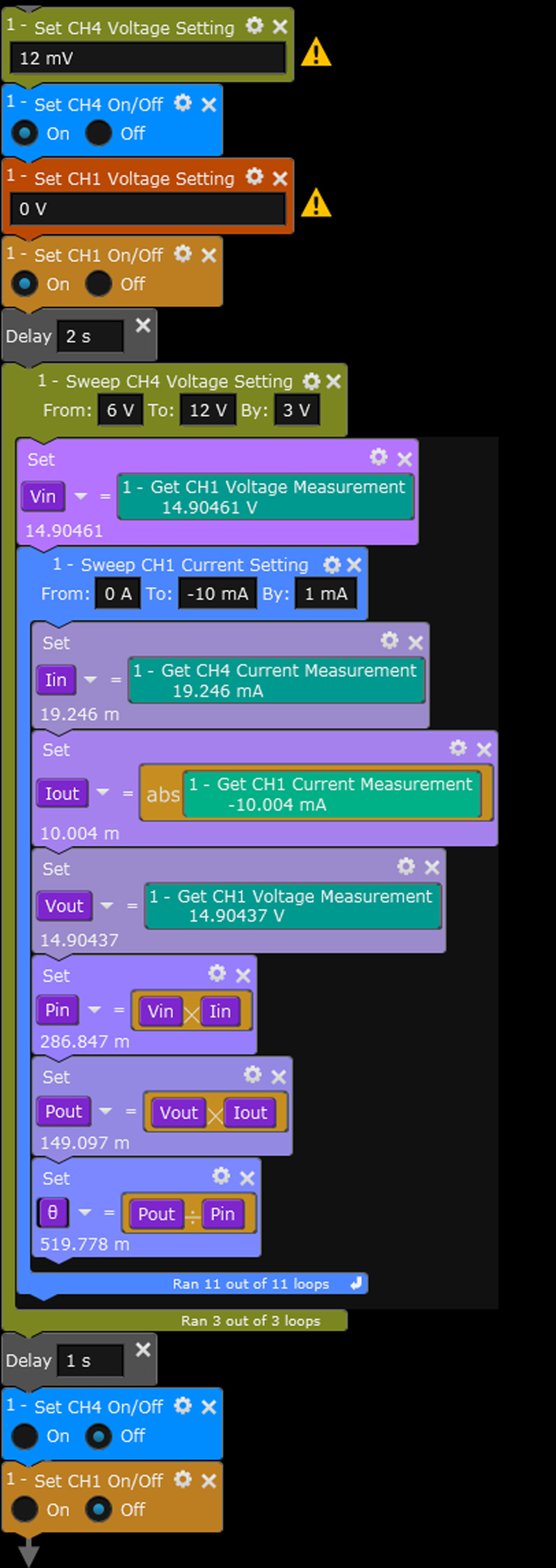
In this example, the DC-DC converter was configured to output a constant voltage of 15 V. The efficiency was measured at three different input voltage values: 6 V, 9 V and 12 V. The load channel was configured to sweep a load current from 0 to 10 mA and measure the output voltage. Figure 2a shows the flow diagram representing the test, while Figure 2b shows the results.
Click image to enlarge
Figure 2a: Efficiency Test Flow

Click image to enlarge
Figure 2b: Efficiency vs. Load Current Results
Load Regulation Test
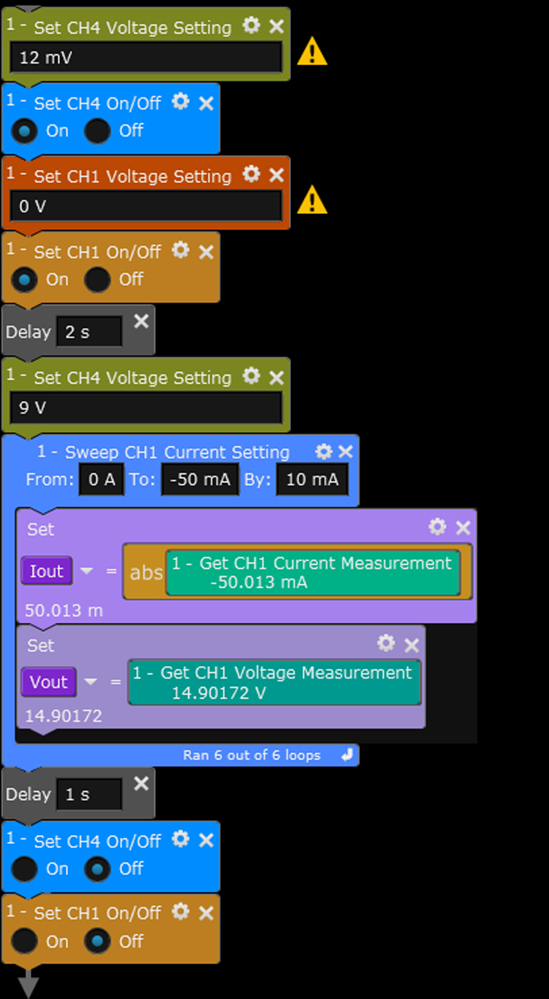
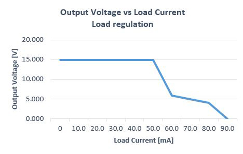
The load regulation test is the capability to sustain the specified voltage output when the load current (Iload) varies at constant input voltage. To execute this test, after powering up the product, you have to slowly vary the output load between the specified minimum and maximum current values. The measured output voltage changes should be within the range specified in product technical specifications. Taking the same connection of the tests described above. Figure 3a shows a test flow to run a load regulation test and Figure 3b shows a typical result of this test when the constant input voltage is applied at 9V and the channel of the DC power analyzer is configured to sweep the current from 0 to 50mA.
Click image to enlarge
Figure 3a: Load Regulation Test Flow
Click image to enlarge
Figure 3b: Load Regulation Results
Line Regulation Test
The line regulation test represents the ability of the DC-DC converter to sustain the specified output voltage while the input voltage is varied between a specified range of voltages. To carry out this test, set the input power source to a value within the input range of the product and power up the product. While monitoring the product output voltage, slowly vary the input voltage between the specified minimum and maximum values. The measured output voltage changes should be within the range specified in the product’s technical specification.
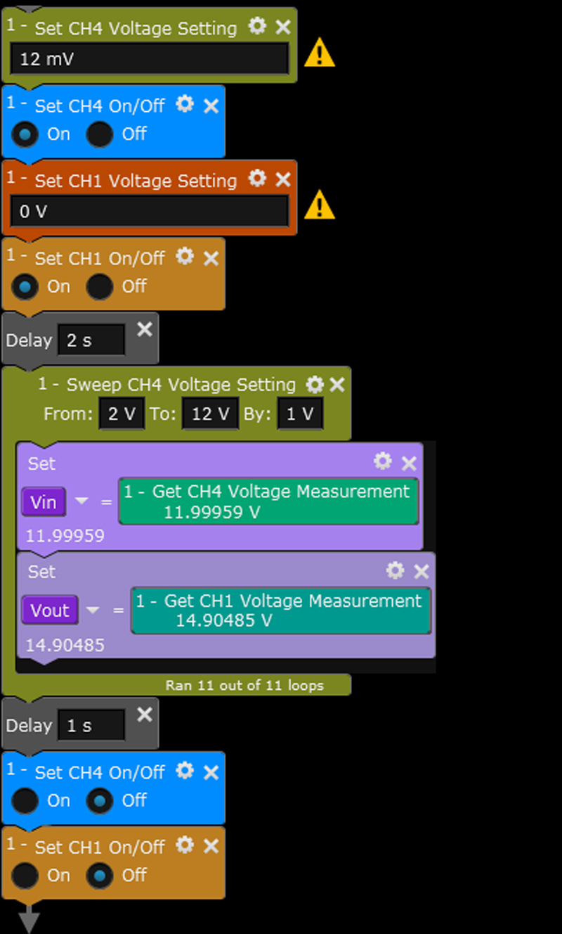
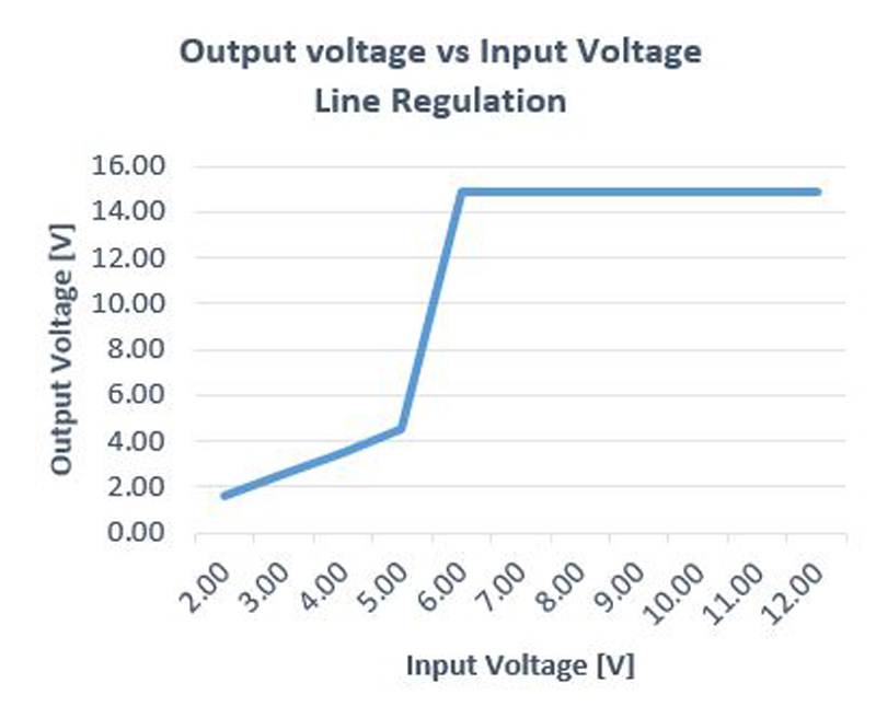
For this test, the channel of the DC power analyzer on the input voltage of the DC-DC converter sweeps over the specified voltage range, while the channel on the output of the DC-DC converter measures the output voltage. Figure 4a shows a test flow to run a line regulation test. Figure 4b shows a typical result of this test when the sweep of the input voltage from 2 to 12 V is applied and the other channel measures the output voltage of the DC-DC converter.
Click image to enlarge
Figure 4a: Line Regulation Test Flow
Click image to enlarge
Figure 4b: Line Regulation Results
In addition to the DC parameter testing performed by the SMU, some tests require the use of an oscilloscope to characterize the AC parameters of the DC-DC converter. These tests include ripple test, start-up time and transient response. To perform these tests, a DC-DC converter test solution may include an oscilloscope.
Start-up Time Test
The start-up time test measures the time delay between and when the input voltage is applied to the DC-DC converter and the time it takes to reach to the steady output voltage. For this test, one SMU channel of the DC power analyzer is applied to the input voltage and one channel of the oscilloscope is connected across the input of the DC-DC converter. Another oscilloscope channel is connected on the output of the DC-DC converter. Using software, the start-up time is automatically calculated. Additional measurements on the signal (e.g., rise-up time, fall-down time, and peak-to-peak voltage) can also be extracted.
Ripple Test
The DC-DC converter has different internal topologies used at different internal switching frequencies that are reflected in the output ripple frequency. The ripple on the output voltage is measured as rejected input noise on the output voltage using an oscilloscope, with one channel on the input and one channel on the output of the converter. The DC power analyzer creates the arbitrary waveform required in this application as a mixed signal comprising a DC signal with a ripple, which is used to power the DC-DC converter.
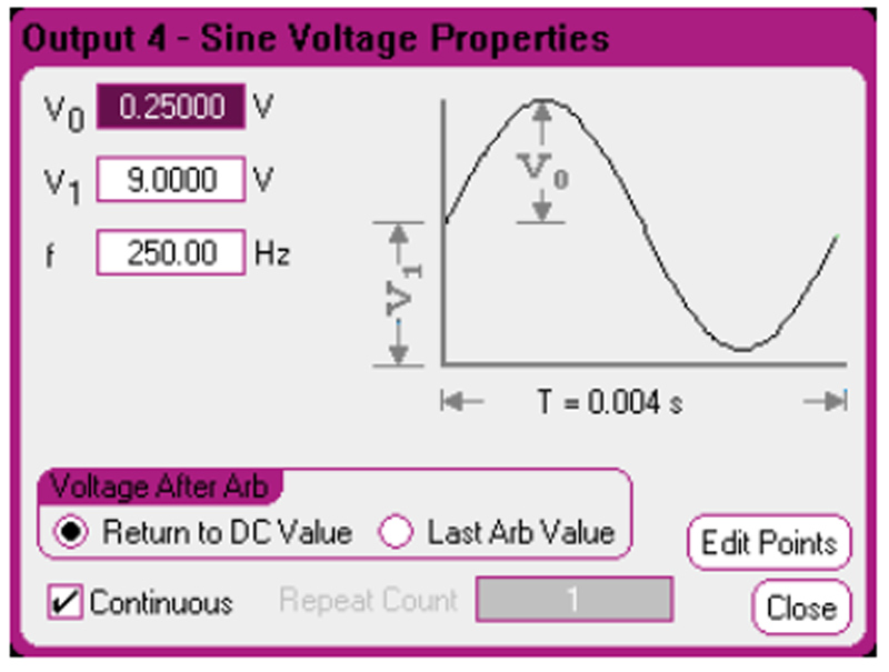
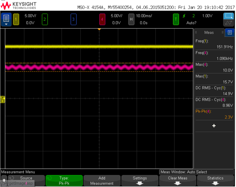
To perform a ripple test of the DC-DC converter, one channel of the DC power analyzer was configured as an arbitrary waveform generator to reproduce a DC signal with a small sine wave added, and one channel of the oscilloscope was connected to the input of the DC-DC converter. Another oscilloscope channel was connected to the output of the DC-DC converter. The voltage peak for the sine wave was 250 mV (v0), the DC voltage was 9 V (v1), and the frequency was 250 Hz (f). Figure 5a shows the arbitrary waveform setup screen of the output voltage used as input voltage to power the DC-DC converter. Figure 5b shows the screenshot of the time-based measurement of the ripple test.
Click image to enlarge
Figure 5a: DC Power analyzer screenshot - arbitrary waveform setup
Click image to enlarge
Figure 5b: Screenshot of the oscilloscope view results
Other Workable Tests on the DC/DC Converter
Another built-in test function of the DC power analyzer should be spectral analysis, which enables designers to analyze the AC components of the output voltage and measure the frequency domain. To cover more power applications such as hybrid electric vehicles (HEVs), uninterruptable power supplies (UPS), and many other bidirectional energy systems and devices that operate at multi-kilowatt power levels, it’s possible to replace the DC power analyzerwith an Advanced Power System (APS) DC power supply. The APS DC power supply covers DC power levels up to 2 kW using the same methodologies presented in this article.
Summary
The tests of DC/DC converters usually require several different instruments and more effort to synchronize the instruments together. The solution, shown in this article, is flexible, with a built-in capability to produce a complete setup to power and test DC/DC converters in a wide variety of test conditions without programming hassles. Related applications of this flexible solution are IC regulator testing, power supply testing, and several charging-system tests.
Keysight Technologies


