How to Protect Against Overvoltages in Analog Front Ends Using Over-The-Top Amplifiers

Figure 1: A simplified representation of the internal structure (taken from ADA4098-1 as the latest generation)
The possibility of high voltages occurring is a constant concern in industrial applications. Finding ways of providing protection from them has always been and will continue to be an important task for developers. This design tip illustrates how developers can accomplish this by utilizing Over-The-Top® (OTT) amplifiers.
Even industrial applications sometimes experience voltages that are higher than the system supply. Although the potentials are not as high here as, say, in automotive electronics, they can often be higher than the usual system voltages. Some of the system voltages may even be too high for many op amps.
This presents a huge challenge to analog front ends (AFEs). Higher voltage scan, for instance, make the internal input diodes of a typical amplifier conduct. The longer this state exists, the more likely it is that a malfunction or even failure will occur. Developers can take the corresponding preventive measures using external protection circuits with, for example, external diodes or resistors. However, these extra components need space on the board and have disadvantages such as leakage currents, additional capacitance, and noise. For this reason, an integrated IC solution with Over-The-Top technology is a top choice.
How Does Over-The-Top Work?
For a simplified explanation, the insides of the latest-generation ADA4098-1 or ADA4099-1 can be considered. These OTT op amp seach have two input stages. The first is a common-emitter differential stage consisting of PNP transistors that work for input signals between the negative supply (–VS) and up to approximately 1.25V less than the positive supply (+VS). The second is a common-base input stage consisting of further PNP transistors that work for input signals whose common-mode voltage is +VS – 1.25V or higher. An example of the internal circuitis shown in Figure 1. The first stage is designed with transistors Q1 and Q2, whereas the second stage has transistors Q3 to Q6.
These input stages thus lead to two different but complementary operating ranges. The offset voltages of the two input stages are tightly trimmed and given in the data sheets.
When the common-mode voltage of the inputs approaches +VS, the second stage is activated and the op amp is then in Over-The-Top mode. This can be a case of overvoltage in various applications. For example, for high-side current measurement, the voltages might exceed the system supply potential due to parasitic or load-related effects, even if temporarily. Typical amplifiers allow signal voltages up to the supply voltage range. If the inputs far exceed this range, internal diodes are usually turned on and a significant electrical current flows through them. Depending on the signal voltage and currents, these spikes can interrupt the operation of the amplifier, or even, in the worst-case scenario, cause the integrated circuit to fail.
Unlike typical op amps, which experience such problems, amplifiers with OTT can tolerate differential input voltages of up to 80 V. In this state, the output level is saturated to the positive supply (+VS). The output retains its ability in this state to sink or deliver current within the datasheet limits. Once the inputs come back to the normal operating range(–VS to +VS), the output level will also return to the usual linear range without any damage to or degradation of the DC accuracy. The case is similar for common-mode voltages of up to 70 V.
Application Examples and Tips for Amplifiers with OTT Technology
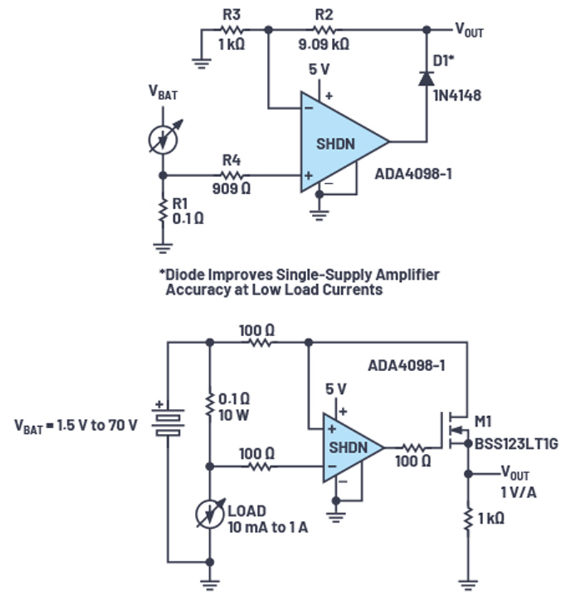
A few current measurement examples can be found in Figure 2. The ADA4098-1 is the low-power version, whereas the ADA4099-1 has a higher bandwidth and a higher voltage rise rate.
Click image to enlarge
Figure 2: Current measurement examples with the ADA4098-1
In the low-side measurement, the gain comes from resistors R2 and R3. Diode D1 improves single-supply accuracy at low load currents.
In the high-side current measurement, 1kΩ and 100Ω (on the top) resistors are decisive for the gain. The resistors at the amplifier inputs provide, among other things, filtering. In this case, a 1% resistor would be optimal. The possible input bias currents result in a voltage drop through these resistors, and close tolerances such as 1% will help to minimize voltage drop ranges here.
The output from the ADA4098-1 can swing under no load from rail to rail within 45mV of both supplies. The output can source 24mA and sink 35mA. The amplifier is internally compensated and can drive a load capacitance of 200pF (min). A 50Ω series resistor can be interposed between the output and higher capacitive loads to extend the capacitive load drive capability of the amplifier.
If the output VOUT drives a circuit with a lower potential and this downstream circuit has protective diodes for its own voltage rails, it would make sense to place a resistor at VOUT. This would limit the possible currents flowing to the downstream circuit.
The ADA4098-1 has a dedicated SHDN pin to put the amplifier in a very low shutdown state when this pin is asserted as high. A logic high is defined by a voltage of ≥1.5V applied to the SHDN pin with respect to the–VS pin. The VOUT pin is then in a high impedance state. As an alternative method, the amplifier can effectively be placed in a low power state through removal of the positive supply. In both of these off modes, OTT is still active and voltages of up to 70V over –VS can be applied to the input pins.
Other uses for the OTT amplifier besides current or power measurements are sensor front ends or 4mA to 20mA current loops. Detailed information, further application examples, and calculations can be found in the data sheet.
Conclusion
This article has demonstrated how Over-The-Top amplifiers can provide protection against overvoltage. Due to the intelligent and precise internal circuit, Over-The-Top amplifiers simultaneously offer robustness and accuracy.
Analog Devices’ fifth-generation OTT amplifiers bring the latest overvoltage protection from the lab toyour circuit design. OTT op amps, such as the ADA4098-1 and the ADA4099-1, deliver higher voltage tolerances beyond the rails while achieving lower offset errors and noise values.