Increasing System Reliability with Redundant Power Supplies

Redundant output power supplies should be considered for equipment where high reliability is paramount, and an unexpected loss of power would cause disastrous results
High-reliability applications include communications systems, both voice and data types, computer systems (volatile memory systems in particular), process controls, utility, transit and municipal systems, and for security / safety alarm systems.
A redundant output power supply consists of two or more complete, physically separate modules, interconnected so that the required output is delivered to the load even when one power supply fails. This is accomplished with a switching arrangement that senses an abnormal output, isolates the defective power supply from the common output points, and substitutes the backup supply.
Basic considerations
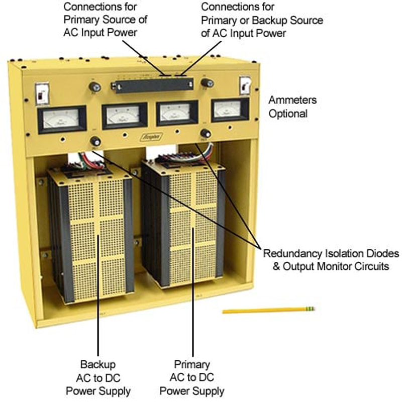
The “backup” supply continues to operate the system while the defective “primary” supply is removed and repaired or replaced. The assembly layout, therefore, must permit easy and safe removal of any supply module while other modules are operating.
Uninsulated high voltage and ac points should be either physically shielded or located where maintenance personnel will not come into contact with them accidentally. Each module should be separately fused, and both its input and output wiring switched by one separate multipole switch per supply. Switching off one supply will then completely isolate the module from the system and prevent any chance of shock to personnel during its removal or replacement.
Although a redundant output supply is primarily intended to prevent system downtime due to loss of output voltage, the possibility of failure resulting from a significant rise in output voltage must also be considered. To prevent this, each power module should be equipped with an overvoltage protector, or crowbar, which effectively short circuits an output that rises to the crowbar’s voltage setting. This insures that the output voltage is always below the crowbar setting and simplifies provision for inter-supply isolation and output voltage monitoring.
Output voltage monitoring circuitry should be simple, highly reliable, and independent of other voltages for its proper operation. It should be fail-safe, and capable of controlling logic, indicators, or alarms operating on other voltages. Wiring a small relay across the output of each supply will be adequate in most instances.
Achieving redundancy
Two basic circuits are used to achieve redundancy. In the momentary-interruptible configuration (Figure 1), a relay switches both input power and the load from one supply to the other. When ac power is initially applied, the backup supply is energized. Momentarily depressing the pushbutton switch applies input power to the primary supply, latches the relay ON, and removes input power from the backup supply. If the output voltage of the primary supply fails, the relay unlatches, and the backup supply is energized and assumes the load.
Figure 1 here (No Caption)
Output power is interrupted during relay switching and until the backup supply voltage rises to its operating level. This configuration, then, finds application only when a power interruption of 50 or 100 msec can be tolerated – as in municipal systems and controls for relatively slow processes.
The greatest advantage of this approach is its efficiency, since at any given time only one supply per redundant output is in operation. Dissipated heat is, therefore, relatively low, a consideration when ventilation is limited and heat build-up is a potential problem. Other advantages are simplicity, ease of setup by untrained personnel, and the capability of closely matching the voltages of both supplies, so the load sees the same voltage regardless of which supply is in operation. And, since interruption of output power switches the relay, it becomes readily apparent if any output power interruption has occurred.
This characteristic, however, is a double-edged sword: until the relay is reset, the output isn’t redundant. Another point to consider is that the backup supply is not energized in normal operation, so its operational status cannot be monitored continuously. Any problems or worse – failures – may not be apparent until the supply is needed. When a momentary-interruptible redundant supply is operated under close supervision and rested frequently, these shortcomings are unlikely to result in an actual system malfunction, but the possibility of their occurrence has limited the use of this configuration.
Power without interruption
The continuously redundant power supply, as its name implies, delivers output power without interruption as long as either power module of the redundant pair is functional. It is the best choice for applications where even a short duration power interruption cannot be tolerated – in communications equipment and nuclear power plants, for example. Both power modules are continuously energized, and their operational status can be constantly monitored.
As shown in Figure 2, the power module outputs are connected to the common output point through diodes. The output voltage of the primary supply is set approximately 0.5 v higher than that of the backup supply. Under this condition, the backup supply’s diode is not forward biased; only the primary supply delivers current to the load. If the output voltage of the primary supply decreases significantly, the situation is reversed and only the backup supply delivers load current. There is no interruption in load current during the transition.
Click image to enlarge
The voltage seen by the load decreases by the difference in the setting of the two power modules, but it is a shift in operating point only; dynamic characteristics, such as regulation, are maintained after the transition has occurred.
Most power supplies sink current from their positive output terminals into their positive sense terminals. But power supplies designed to sink positive sense current into their positive output terminals are more appropriate in continuous redundancy applications. With the first approach, eliminating power supply interaction via the sense lines is extremely difficult. With the second, a resistor is necessary to insure sense current flow through the sense line diode of the supply with the higher output voltage. This forces sensing of the voltage at the common output point.
Multiple outputs
If multiple redundant outputs with the same ratings are required, the necessary number of primary supplies can be supported with a single backup supply. This can b accomplished in the continuously-redundant configuration. A functionally similar arrangement based on either configuration can also be used. Since it is unlikely that a second supply will fail within the time required to correct the previous failure, the advantage of redundancy is realized at a considerable cost savings. The degree of redundancy is defined as 100% divided by the quantity of primary supplies supported by one backup supply.
Input power redundancy
The most effective redundant output power supply can keep its load operating only when input power is present. Here too, the concept of redundancy may be used. If two independent sources of ac power are available, one power supply of each redundant pair can be operated from one source; the remaining supplies operate from the other independent source. Unfortunately, so simple a solution is not always possible, and an emergency power source must be provided.