Digital-control method improves PFC performance
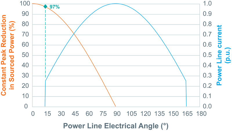
Figure 1: Converter input power vs. line current with a symmetric conduction angle, constant current peak and resistive load.
Traditionally, PFC (power-factor-correction) controls present a purely resistive behavior with respect to the power line. By means of multiplier or equivalent blocks, front-end converters draw a current the shape of which closely follows the input line voltage. This approach presents one issue: the converters operate over a condition range that is far from optimal, particularly in close proximity of the power line's zero crossing. An alternative approach implements a digital control that forces a particular line-current shape, which avoids the issue while meeting all applicable EMI and EMC standards. Moreover, an improved algorithm reduces line-voltage harmonic propagation to the line. Background Circuit designers have addressed PFC control in a variety of ways over the last twenty years. The majority focus has always been on the quality of converter's control technique and the result in terms of PF and input-current THD (total harmonic distortion). While the most common converter topology has been the non-isolated boost, the need for isolated low-output-voltage products led to the development of single-stage isolated topologies. Design constraints add up quickly, however, and force less-than-optimal component sizes and ratings. To minimize those constraints, more recent research focuses on radical approaches that actively modulate some reactive elements. These methods achieve better performance at the expense of available headroom on power factor and line-current THD with respect to IEC standards. In both the industrial and consumer environments, electricity is processed from raw AC, as distributed to homes and industrial plants, to a variety of DC levels. As electronic converters overcome the number of linear loads, such as incandescent lighting or heating, the need for PFC arises to avoid unnecessary losses on the power-distribution system and to meet the stringent regulations utility providers enforce. There are several traditional PFC approaches within consumer and industrial markets. These include distributed active PFCs within individual equipment such as PCs, washing machines, and TV sets in contrast to centralized, plant-level devices such as active power-quality compensators. The approach the consumer market takes is rapidly expanding into industrial segments, where it's become more effective to deploy equipment with embedded PFC. In fact, industrial plants today include a diverse set of equipment: uncompensated non-linear electronic loads and PFC-managed ones. The control system that PFCs such as Vicor's PFM use avoid propagating spurious harmonics legacy electronic loads generate and provide significant benefits to the utility line in terms of overall power quality. Avoid operation near power minima Every switch-mode power supply presents an efficiency curve that quickly approaches zero when minimal power is processed. In PFC applications, the goal is to present a purely resistive behavior with respect to the input line, aiming for sinusoidal input power to the converter. The nature of this task implies a variety of tradeoffs:
- CCM (continuous-conduction mode), constant frequency operation enables optimal powertrain design, but operates the converter efficiency curve close to zero at line crossings.
- DCM (discontinuous-conduction mode), variable frequency operation enables better efficiency, but the powertrain and magnetics designs are suboptimal.
- Hybrid approaches such as burst-mode or hysteretic converters present EMC and EMI challenges.
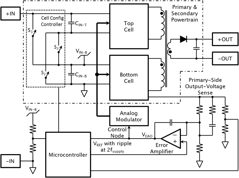
Implementation In the PFC block diagram, two primary-stage cells magnetically couple with a single-ended secondary stage, while their inputs are configurable in either series or parallel with respect to the rectified power line (Figure 2). This approach provides several benefits, the most notable being the invariance of efficiency with respect to the input voltage. Controls, which appear at the bottom of Figure 2, consist of a classic analog voltage-regulation loop. This loop manages the control node of an analog modulator to control the converter's output voltage. The microcontroller implements the algorithm: the analog loop reference is actively modulated based on input and output voltage, to achieve power factor correction and shape the input current appropriately. It is important to note that the microcontroller only needs input line frequency and phase information to enable the powertrain outside the dead-band around the line's zero crossing. Although the controller samples the input voltage at a relatively high rate, line frequency acquisition requires few line cycles. This is a minor task for the digital control, resources of which apply to achieve power factor correction and shape the line current. The conduction angle forced on the line current is responsible for 14% of THD. However, the circuit meets all applicable EMC standards. Propagation of line-voltage harmonics Classic PFC relies on direct or indirect measurement of the line voltage, which the controller uses to shape the input current. In cases where the line voltage presents greater harmonic content (typically in heavy industrial environments), the following issue can arise: The current drawn by the input line closely follows the shape of the input line voltage. Harmonics on the voltage waveform is also present in the current waveform, which causes further line drops with the same harmonic content, therefore compounding and worsening the overall power-distribution quality. PFCs often use active compensators in these cases, in order to meet utility regulations, but add operational costs. An alternative approach uses a digital algorithm, with the objective of obtaining a line current shape that meets all applicable IEC standards, achieves high power factor, but does not propagate line voltage harmonics. The technique's targets are:
- To maintain the ratio between input voltage and input current constant, therefore achieving PFC
- To maintain constant the ratio of the input voltage's moving average to the input current's moving average to reduce, and in some cases even cancel, harmonic content in the current waveform.

Equation 1 summarizes how this is achieved: and are the instantaneous values of the converter input voltage and the control node voltage, respectively (as shown in Figure 2), while and are their moving average values. The introduction of the average term effectively causes a phase delay and affects the power factor by about 1%. The term also significantly reduces line-voltage-distortion propagation to the converter's input current, because higher-order harmonics whose periods falls within the averaging window are reduced over several sampling periods within the modulation algorithm.
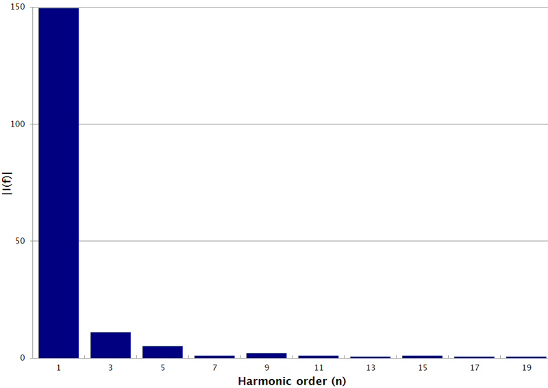
Figure 3 shows the harmonic content of a 120 VRMS sinusoid clipped to 80% of its amplitude.
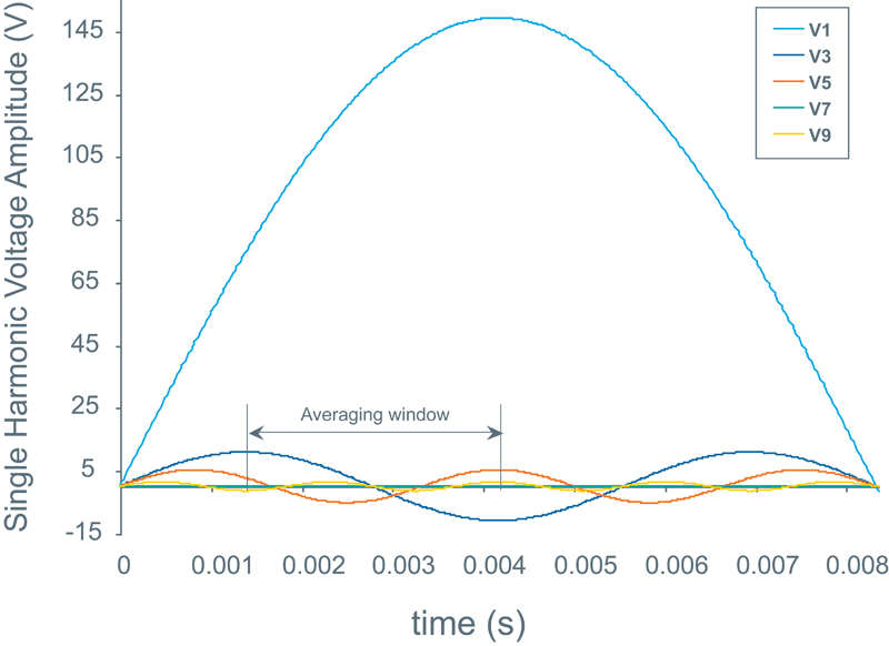
Figure 4 shows those harmonics individually in the time domain, with an averaging window for the digital control, which helps to visualize how, by managing sampling rate and window width, higher harmonics are practically canceled. www.vicorpower.com