Installation of Open Frame, U Channel AC/DC Power Supplies
Safety, EMC and thermal management are just some of the considerations required when installing open frame and U channel power supplies.
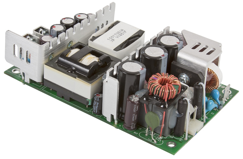
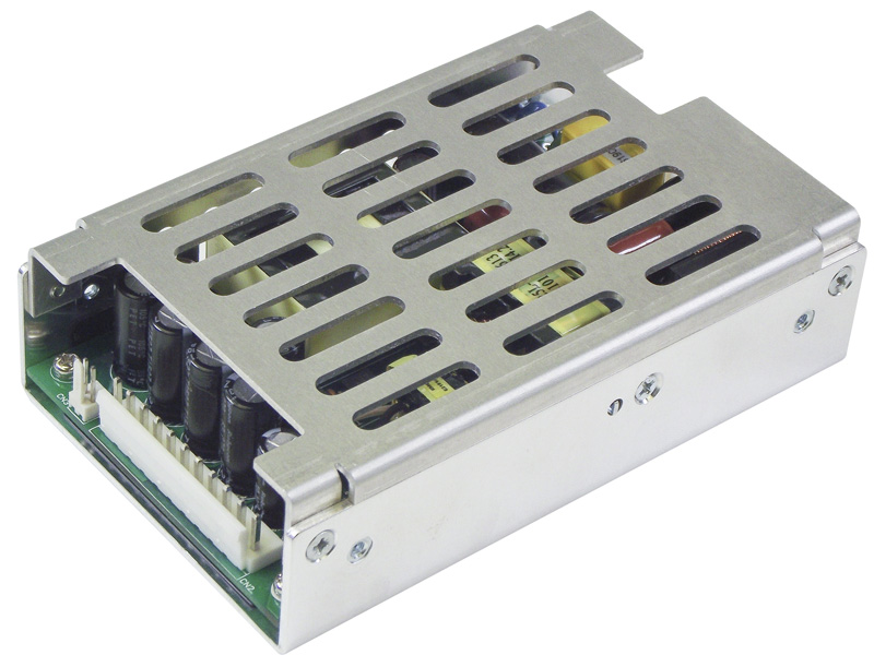
Figure 1: Open frame power supply
AC/DC power supplies are commonly supplied in what is known by the industry as an open frame format. Open frame generally describes a product which is a PCB only construction, component power supply designed to be installed into an end-equipment application which provides the enclosure for the entire product.
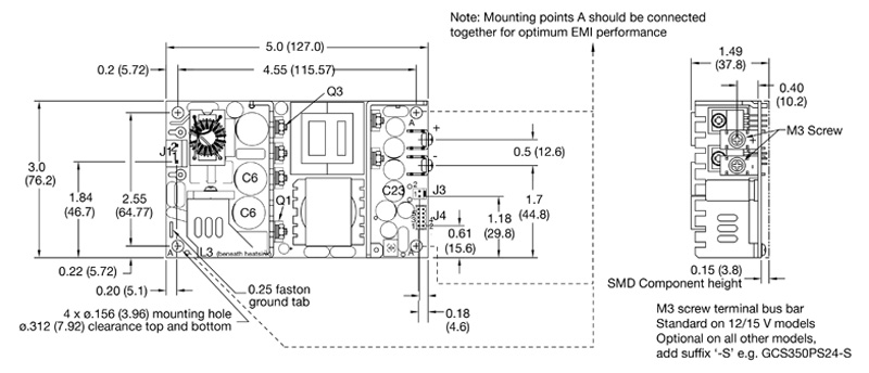
Another common format for power supplies for integration into end equipment is the U channel where the power supply PCB is installed in a U shaped, usually aluminium, chassis which is often used as a part of the thermal management of the power semiconductors as well as providing multiple fixing options for the equipment manufacturer to install the supply into the final assembly.
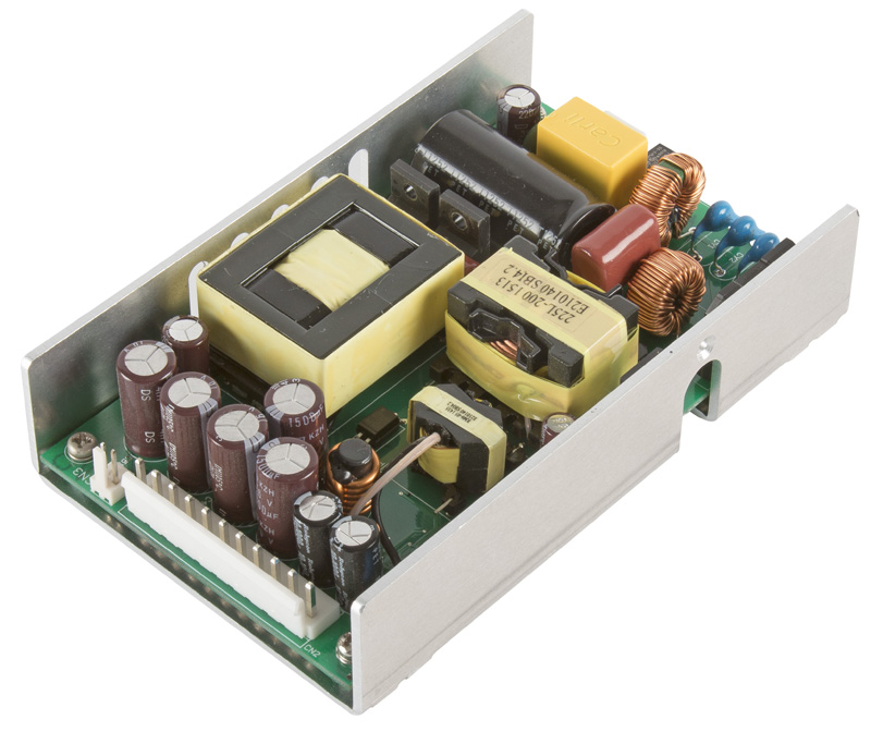
Click image to enlarge
Click image to enlarge
Figures 2a and 2b: U channel power supply with and without cover
There are several considerations when installing open frame and U channel power supplies, principally these are related to safety, electro-magnetic compatibility (EMC) and thermal management and these areas of concern are discussed here.
Another important consideration is the detailed specification of the power supply, especially with regard temperature and input voltage de-rating, when compared to the data sheet headline power rating. The best products maintain the rated power to 50⁰C ambient temperature and down to 90VAC input, while some products advertise a headline power rating with derating of up to 20% at low line and de-rate the available power at ambient temperatures as low as 40⁰C, which may make these products unsuitable for the end application.
Safety
When mounting an open frame power supply into the equipment enclosure, it is necessary to observe the required creepage and clearance distances to the equipment enclosure to all faces of the supply. In a class I system this will mean ensuring 3 or 4mm between any earthed metal part and any primary part of the power supply, depending on whether the end application is industrial or medical, which may necessitate the use of insulators around the power supply assembly.
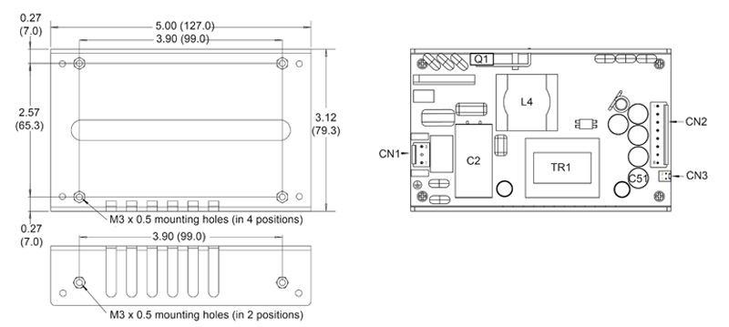
Click image to enlarge
Figure 3: Mechanical drawing of open frame supply showing mounting point ground connections
Where a class I power supply is employed the safety ground connection to the power supply is an integral part of the electrical safety system and must be securely connected to the equipment safety ground. This connection is generally made available via one of the mounting holes, via the AC input connector or via a faston style tab on the power supply PCB. There is likely to be more than one earth connection to the assembly required which affects the electrical emissions and susceptibility performance and is discussed later.
Click image to enlarge
Figure 4: Typical mechanical details of a U channel power supply detailing fixings and connections
Where a class II power supply is employed the creepage and clearance distances may be required to be Larger in metal enclosures though often the equipment enclosure is non-conductive where these units are employed.
U channel construction eases the issues surrounding safety as the U channel chassis is connected to the supply’s safety ground and can be bonded directly to the equipment enclosure along with the power supply safety ground connection. The requirements for safety clearances between the PCB and the surrounding U channel are catered for in the design. However, the ends of the U channel and the top face of the assembly are usually still open and care must be taken in these areas to ensure adequate creepage and clearances distances are maintained.
U channel construction has the additional benefits of ease of handling and ease of installation. The U chassis provides a more rugged construction and incorporates threaded mounting holes for use by the installer, reducing the mounting hardware to a simple screw fixing. Care must be taken to observe any maximum screw insertion penetration depth to maintain safety creepage and clearance distances.
Another U channel construction benefit is the potential for additional cooling of the power components by conduction cooling to the equipment enclosure reducing both the temperature of the bonded components and consequently the general temperature within the U channel construction.
Both open frame and U channel power supplies include one or sometimes two, in the case of products designed for medical equipment applications, input fuses which are also integral to the overall product safety system design and protect against fire hazard in the event of catastrophic failure. This fuse is usually permanently installed in the power supply and is not designed for replacement as the only reason for clearing of the fuse is failure of the power supply assembly.
As both constructions require input cabling, the end equipment also requires additional fusing to protect against potential fire hazard issues created by the incorporation of connectors, indicators, switches and the cabling itself.
Output cables must be sized to accommodate the maximum power capability of the power supply including the maximum tolerances for its overload protection specification to ensure safe operation in the event of a fault in the equipment itself.
There are also thermal considerations to take into consideration as some safety critical components have a maximum temperature rating, this is discussed in more detail later under thermal management.
Electro Magnetic Compatibility (EMC)
Open frame power supplies normally require two and sometimes three mounting points to be connected to ground. As discussed above, in a class I system usually one of these connections is required for safety ground and is located on the input side of the assembly, this connection will also connect the line to ground and neutral to ground common mode filter capacitors, also known as Y capacitors. These Y capacitors work in conjunction with the common mode inductors within the power supply assembly to attenuate noise associated with rapid changes in voltage in the supply’s power stage. The other or others are usually on the secondary side and connect the output common mode filter capacitor(s) to ground. The differential element of the filter which is designed to attenuate the noise associated with rapid changes in current is contained within the supply in the line and neutral connections.
This output common mode capacitor is integral to the EMC performance of the power supply and must be connected for optimum EMC performance. Where the equipment uses a metal enclosure this is rarely an issue. In plastic enclosures, either in class I or class II configurations, it is necessary to make other provision to connect these points together to ensure EMC compliance. The points which require connection to ground or together are usually identified in the power supply data sheet as in the following example.
The optimal way to connect these points is by mounting the open frame supply on a metal plate which need not be connected to anything else but provides a low impedance path with low parasitic elements for the filter capacitors to be connected.
Where this type of mounting is impractical then other methods must be employed to connect these mounting points such as a multi-strand cable.
In a U channel construction, all ground connections are made within the U channel enclosure simplifying the installation of power supply from an EMC perspective. Good electrical bonding from the U channel chassis to the equipment enclose via multiple fixing points is also beneficial, minimising parasitic elements.
In both cases the input and output cables should be kept well apart and avoid close proximity to the open assembly to avoid potential issues with radiation from the switching components and magnetic assemblies within the power supply being induced into the system creating potential conducted and radiated emissions issues for the end equipment.
Thermal management
Open frame power supplies may have a power rating when convection cooled, force air cooled or both. In the case of U channel supplies there may also be a conduction cooled rating utilizing the equipment enclosure or external heatsinking for further cooling of the assembly.
The mounting position, orientation, available surrounding space, applied load and surrounding parts along with any system air cooling are unique to each application. It is important to check the operating temperature of key components within the power supply assembly once installed to ensure that the safety critical components do not exceed their maximum ratings as specified in the safety approval reports and that the reliability and service life of the supply are not impaired.
Data sheets for both open frame and U channel power supplies deigned for integration into and equipment, commonly identify the key safety components & their maximum temperature ratings which vary from one supply to another depending on the class of insulation system employed. They typically also provide an estimated service life curve based on the temperature of key electrolytic capacitors, which are the only parts with a wear out mechanism within the power supply.
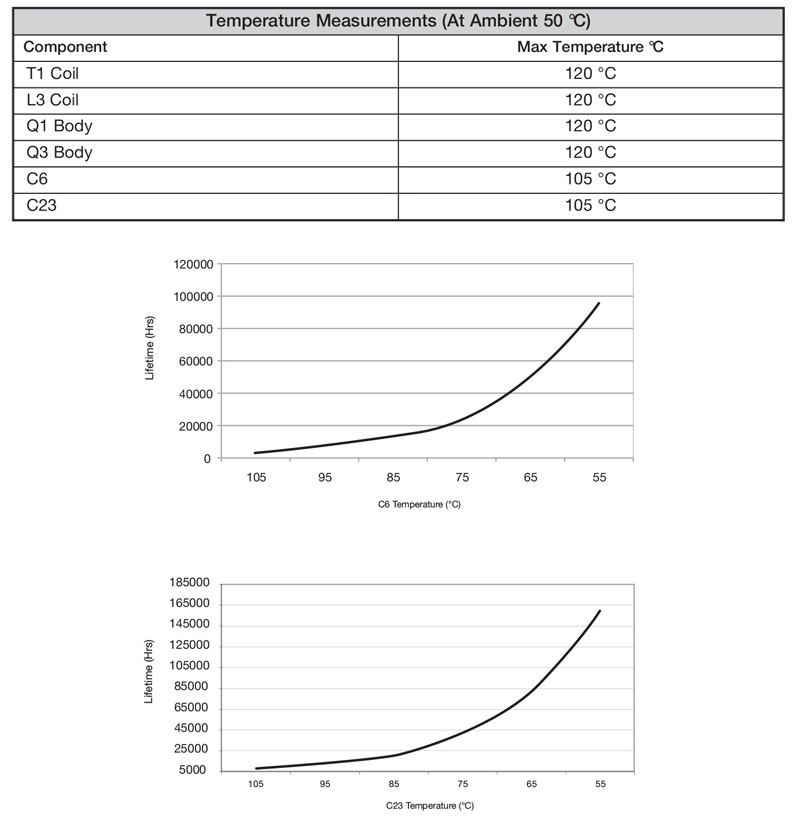
Click image to enlarge
Figure 5: Table and graphs showing safety limits and estimated service life for 24/7 operation
Service life predictions are based on the electrolytic capacitor design lifetime at its maximum temperature rating and the average temperature experienced in the end application over its mission profile. Clearly the maximum temperature rating cannot be exceeded under any circumstances or extremes of operation.
All electrolytic capacitor lifetime calculations are based on the Arrhenius equation, where the rate of reaction halves and hence the lifetime doubles for every ten Degree Celsius reduction in temperature, making this a critical element in the service life or service interval of the entire end application. Lifetime calculations undertaken by the power supply manufacturer will include elements based on the applied ripple current but, as this is impractical in the finished power supply assembly, a good indication of service life can be determined by measurement of the component case temperature and application of the Arrhenius equation to the to the specified temperature and design lifetime.