Currently, more than seven billion IoT devices are in use worldwide, and the number of active IoT devices is expected to grow
Of all the “hot” electronics markets, none is hotter than the market for devices designed to interact with the Internet of Things (IoT). Currently, more than seven billion IoT devices are in use worldwide, and the number of active IoT devices is expected to grow to 22 billion by 2025. Virtually all of those devices need to be powered or recharged in some way, often with USB cables in the case of portable or wearable objects. Consumers’ desire to recharge their wireless IoT devices quickly and the higher levels of power required to do that raise the risk of thermal damage for both the charging cable and the device itself. As these devices get smaller and more transportable, their ports are increasingly exposed to debris in pockets, bags, and the atmosphere itself. These contaminants, when trapped between the device’s or connector’s power pins, can produce faults that lead to over-heating, especially at the higher power levels being used to charge the latest devices.
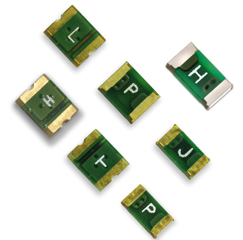
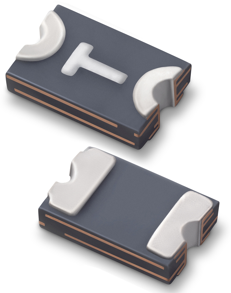
Chargers with various versions of USB cables and connectors have been used for years to recharge mobile and wearable devices. The challenge for manufacturers is to provide effective over-temperature protection for both USB charging cables and IoT devices. Polymeric Positive Temperature Coefficient (PPTC) devices (Figure 1) are among the devices traditionally designed into the connectors of USB cables to provide over-temperature protection. However, the development of USB Type-C and USB Power Delivery (USB-PD) specifications and the higher levels of power they support (up to 100W) are driving the development of innovative protection solutions.
Charging Essentials
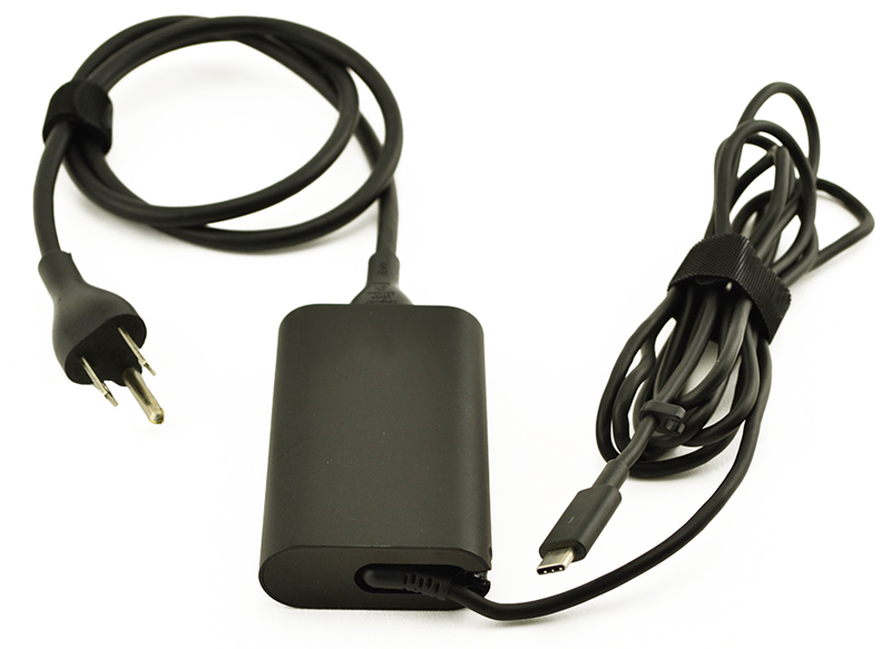
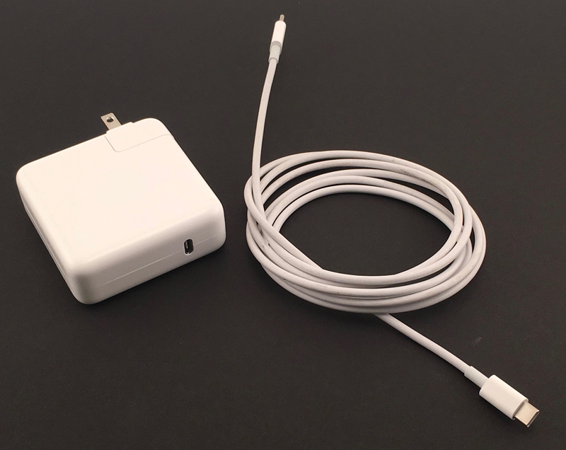
USB Type-C (often shortened to USB-C) cables are equipped with one or more symmetrical (and therefore, reversible) 24-pin connectors with a low-profile 8.4 mm × 2.6 mm form factor. USB-C chargers have an AC plug on one end and either a cable with a USB-C connector on the other (for plugging into the device to be charged) as seen in Figure 2 or a USB-C output port that allows plugging in a USB-C cable as seen in Figure 3. When recharging a device, the cable, the charger, and the device being chargedmust all work together.
Click image to enlarge
Figure 2. Typical USB-C application with AC plug and captive USB-C cable
From a protection standpoint, USB-C cables must be capable of carrying appropriate voltages and currents. For chargers with captive or fixed cables, the cables must be capable of handling the charger’s maximum voltage output. Cables with Type-C connectors on each end must be capable of handling 21V and at least 3A. Those that include special e-marker ICs can carry 5A of current. Any device placed in the path of power, especially protection devices, must also be capable of withstanding these voltage and current levels.
Click image to enlarge
Figure 3. Typical USB-C application with AC plug and independent cable
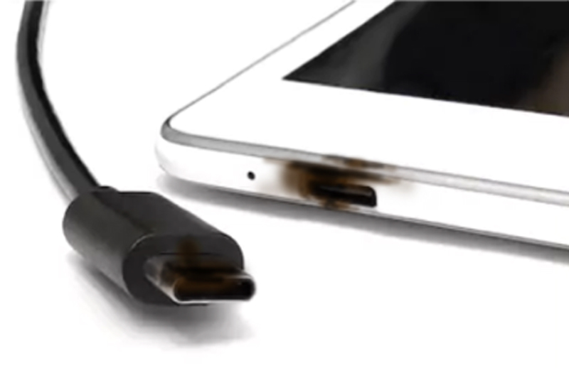
USB-C cables are susceptible to damage from two different factors. The first factor is the connector’s susceptibility to contamination and the associated risk of uncontrolled overheating. The pin pitch of USB Type-C connectors is 0.5 mm―much tighter than the 2.5 mm pin pitch in USB Type-A connectors. This tighter pitch significantly increases the risk of a fault that could cause a thermal event When dust, metal particles, hair or other debris gets stuck in a USB Type-C cable connector or the connector pins become deformed, it can create a resistive fault from the power line to ground. These resistive faults can cause a dangerous temperature rise while increasing current by only a minimal amount. The result can be damage to both connectors and device ports (Figure 4). The second factor is the higher level of power these cables are being tasked with carrying today—some as high as 100 W. When this level of power flows through a fault, it can produce significantly more damage than a lower level of power through the same fault.
Click image to enlarge
Figure 4. Resistive faults in USB-C connectors can damage both cables and the IoT devices being charged.
As mentioned previously, the traditional approach to protecting USB cables from overheating damage involves locating a protection device on the VBUS power line. The protection device would be placed on a printed circuit board inside the connector to sense the temperature rise created by the resistive fault. However, when attempting to protect up to 100W of power, using this approach can challenge power supply design engineers.
One of the drawbacks of adding a protection device in the path of power is that its resistance, even if it’s just milliohms of resistance, can contribute to meaningful power loss, making it more difficult for power supply manufacturers to meet mandatory efficiency requirements. It also can be difficult to fit the device into the close confines of a USB-C connector. For example, the PPTCs suitable for protecting 60 W chargers typically have a 1210 (3.2 × 2.5 mm) footprint. A PPTC needed to protect a 100 W charger would be even larger. Although locating a PPTC on the VBUS line remains a reasonable option when designing cables for power levels up to 20‑25 W, a new generation of digital temperature indicators combine a compact 0805 footprint (2.0 × 1.2 mm) with a better over-temperature protection solution for higher power charging.
Click image to enlarge
Figure 5. PolySwitch setP digital temperature indicators combine a compact 0805 footprint with a rigid design that can stand up to automated assembly and molding processes.
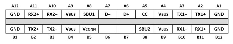
Compact digital temperature indicators like the PolySwitch setP (Figure 5) employ a different method for over-temperature protection for USB Type-C cables and IoT devices than earlier solutions. Instead of being placed on the VBUS line, they are designed to be placed on the communication channel (CC) line (Figure 6). They comply with USB-IF’s USB Type-C specifications and can help protect even the highest levels of USB Power Delivery (100W).
Click image to enlarge
Figure 6. Functional signal plan for a USB Type-C plug
When a damaged connector pin or debris caught between the connector pins creates a fault that causes the cable’s temperature to rise higher, setP switches from a low resistance state to a very high resistance state, causing the voltage on the CC line to rise higher than the “vOpen” value defined by the USB-IF. This vOpen value is used to determine if the source and sink are detached. Once the system thinks the source and sink are disconnected from each other, power on VBUS is turned off, thereby preventing the device from overheating. Once the user disconnects the cable and removes the debris, normal charging can resume.
This approach offers a variety of benefits to the charging system designer and the end users. The setP indicator is not only about half the size of other solutions, but it also has a rigid structure that can stand up to typical cable assembly and molding operations. That makes it suitable for use in USB Type-C charging cables, USB Power Delivery charging cables, and chargers with captive USB Type-C cables.
Conclusion
USB-C cables offer IoT device owners a fast, uncomplicated way to charge their devices and transfer data. Now, with the development of a new approach to over-temperature protection, they can be confident that the process will remain safer as well.
Littelfuse