Replace halogen bulbs with well-driven LEDs
LEDs are increasingly used in 24VAC and 12VAC lighting systems as a robust, energy efficient and high performance alternative to halogen lamps. Power converters that drive the LEDs should have a high power factor (above 90% in order to meet generally-accepted green standards), should be efficient, use a minimal number of components and should run cool. They do not need isolation.
One solution that meets these requirements combines a rectifier bridge and a current-controlled synchronous step-up/step-down converter. Specifically, a synchronous 4-switch buck-boost converter can be paired with a 4-switch ide-al diode rectifier bridge for high power LEDs; lower power solutions can use a standard diode bridge. Both solutions are shown here.
For example, the LT3791 60V 4-switch synchronous buck-boost controller IC can drive constant current (either DC or pulsating) into a string of high power LEDs. It features an output current feedback loop used to drive constant current through a string of LEDs, and a CTRL dimming input pin that can be tied to the 120Hz half-sine wave output of a rectifier bridge to create a high power factor pulsating LED current output.
A device such as the LT4320 is an ideal diode rectifier bridge, as it drives four MOSFETs in place of four typical rectifier diodes, for highest efficiency conversion of the 60Hz 24VAC input to 24VRMS 120Hz pulsating output. When currents reach 5A and higher, the diodes in a standard rectifier bridge dissipate significant power and heat up. The LT4320 helps high power AC applications run efficient and cool by driving low resistance external N-channel FETs.
98.1% power factor
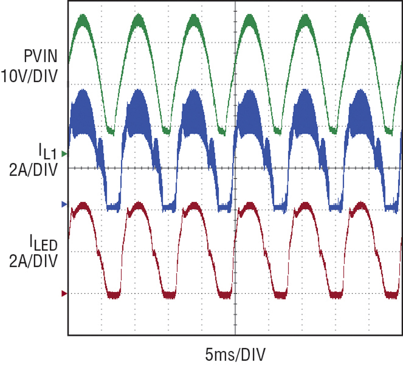
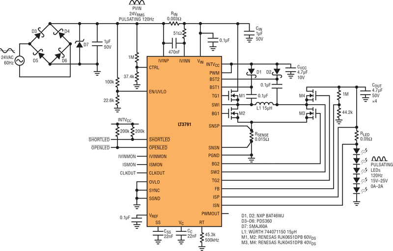
Figure 1 shows an LED driver that operates with 98.1% power factor directly from 24VAC. It can drive up to 25V of LEDS with 120Hz pulsating power with LED current peaking at 4.4A. At 120Hz, the pulsing of the light is not detectable by the human eye and is seen as constant brightness. The high power factor 24AC input voltage and current waveforms are shown in Figure 2. The 10Hz pulsating LED current waveforms are shown in Figure 3.
Click image to enlarge
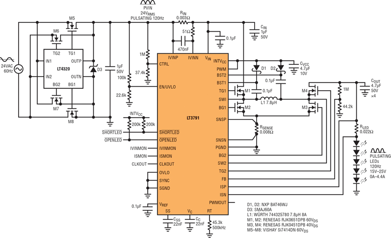
Figure 1. 24V AC to 60W LED driver (600W halogen equivalent) features high power factor & high efficiency
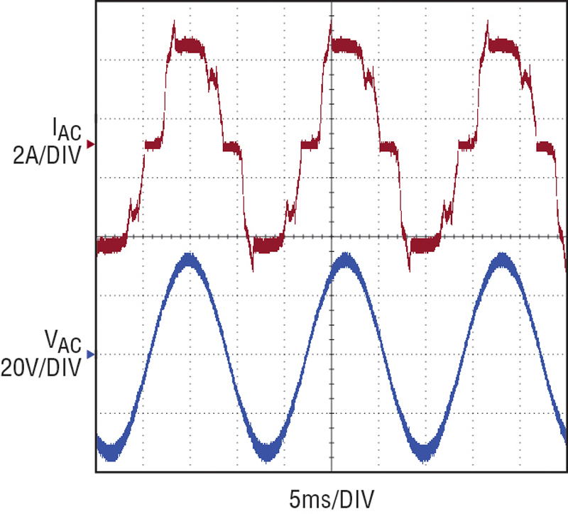
Figure 2. 60Hz 24VAC input waveforms
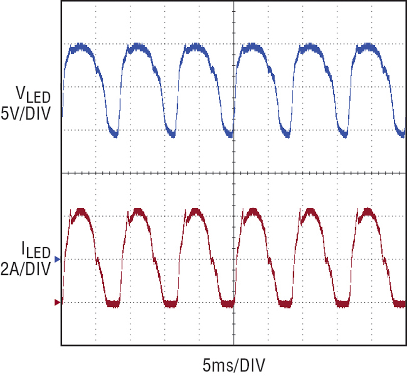
Figure 3. 120Hz pulsating LED driver waveforms
LED current foldback with the CTRL pin voltage is used to achieve the high power factor. The maximum LED current is set by RLED at 4.5A, but the CTRL pin monitors the post-rectifier 120Hz PVIN input voltage (see Figure 4) and shapes the LED current waveform to match the input. When the input drops below the shutdown pin threshold, the IC goes into shutdown and switching stops. The LED current trails off as the output capacitors are discharged and soon enough, the input rises above the shutdown pin threshold and the LT3791 starts back up. With the CTRL pin folding back the LED current at low input, start-up is not harsh and inrush currents do not affect the high power factor.
Click image to enlarge
Figure 4. 120Hz pulsating PVIN
High efficiency & high power factor 60w pulsating led driver
The 24VAC pulsating LED driver converter in Figure 1 delivers approximately 60W of LED lighting at 94% efficiency. This eco-friendly solution is roughly equivalent to 600W of halogen lighting replacement without using lead, mercury, argon, and Xenon or krypton gases. The four synchronous switches of the LT3791 buck-boost converter and those of the LT4320 ideal diode bridge are responsible for the high efficiency.
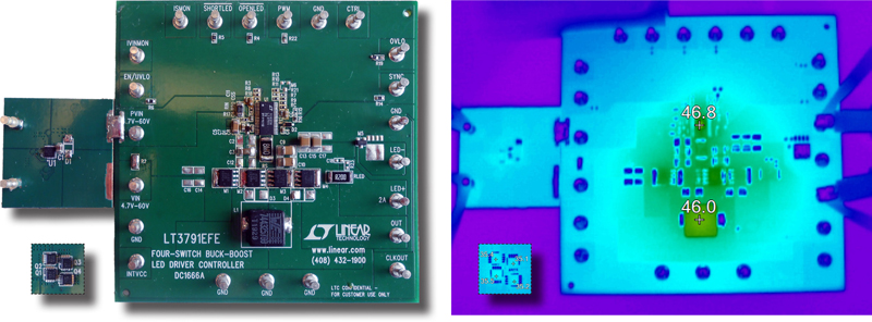
Figure 5 shows the circuit components remaining cool despite the 60W conversion. The components have less than 24°C temperature rise, showing that there is plenty of room to spare for even higher power applications. A standard rectifier bridge would produce about a 50°C temperature rise and run several efficiency points lower.
Click image to enlarge
Figure 5. Components remain cool in the high efficiency LED driver shown in Figure 1. Note that the LT4320 ideal driver remains cool at full LED current.
Total efficiency is calculated by measuring the input power, the power factor, and the delivered output power separately. The values of 63.0W real input power, 64.4W apparent input power and 98.1% power factor are measured with an HP 6812A AC power source.
Measurement of the output power is a bit more complex. A current probe and oscilloscope are used to capture the pulsing current and voltage waveforms at the output of the converter. From these waveforms, the converter output RMS current and voltage is calculated for the on-time (tON) of the LED. The on-time output power is POUT(ON) = VRMS(ON) • IRMS(ON). Output power is zero during LED off-time, where the current is zero. The output power of 60W is calculated via a simple duty cycle equation: POUT = POUT(ON) • tON • 120Hz. Overall efficiency = output power divided by real input power.
High efficiency & high power factor 24w pulsating led driver
The circuit in Figure 6 is a high efficiency and high power factor 24W pulsating LED driver that operates from 24VAC input. Because the power level here is less than half of the 60W LED driver in Figure 1, the rectifier bridge shown in Figure 6 is made from four discrete Schottky diodes, instead of ideal diodes. The trade-offs for simplicity are slightly lower efficiency and additional heat dissipation.
Click image to enlarge
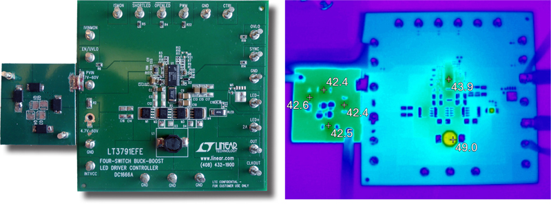
Figure 6. Alternate, 24W solution uses a standard diode rectifier for simplicity
The principals of the 24W circuit are the same as the 60W circuit and the two operate in the same manner. Efficiency of the 24W circuit is 90%, lower than the 94% achieved by the 60W circuit. Nevertheless, this loss is acceptable due to the overall lower power, making the temperature rise in the discrete rectifier bridge components comparable between the two.
With the discrete diode rectifier bridge, the components only heat up to 49°C as shown in Figure 7, well within the requirements of most high-power LED drivers. For higher efficiency, simply replace the discrete rectifier with a LT4320-based rectifier. In general, as power levels and temperatures rise, the need for synchronous rectification in both the converter and rectifier goes up.