Author:
Tobias Fuhr, development engineer, Finepower GmbH & Tobias Herrmann, Field Application Engineer, Finepower GmbH
Date
01/15/2019
 PDF
PDF
Click image to enlarge
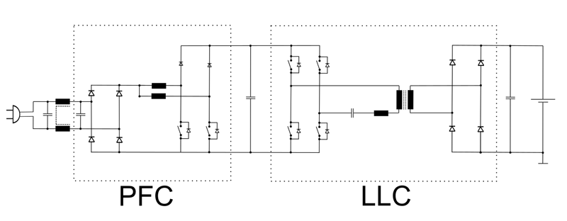
Figure 1: Conventional two-stage topology for a single-phase, electrically isolated on-board charger consisting of power factor correction circuit (PFC) and resonant DC/DC converter (LLC)
BMW, Tesla, or Volkswagen - every car manufacturer uses an increasing number of electrical systems in its latest models. Whether for safety, driving assistance, comfort or entertainment, the electrical energy demand in cars is constantly growing. This is accompanied by an evolution of power supply systems in cars from 48V batteries in mild hybrid systems with starter-generators to the peak of electrification, at which the purely electrically powered car (BEV) with a high-voltage battery stands.
For these vehicle types, a visit to conventional filling stations for refilling fuels is no longer an option. Instead, it is necessary to charge the battery with electrical energy. This can be done advantageously via DC (fast) charging columns, which already provide the direct current required by the traction battery and thus enable efficient and fast charging. Currently, these DC charging points are still very rare and can often be found along main traffic arteries.
To offer a universal possibility for charging, a so-called on-board charger (OBC) is carried as a charger in current electric vehicles, which converts the typical alternating voltage of the supply network into a suitable charging direct current. AC charging columns, wall charging stations for home installation in your own garage or, with additional safety monitoring, conventional sockets can also be used to charge the electric vehicle.
The fact that in this case the entire charging electronics is permanently installed inside the vehicle is the decisive difference to DC charging with stationary external charging electronics. In view of the limited resources in terms of installation space and weight in the vehicle, as well as the objective of low additional costs, on-board chargers are only suitable for smaller outputs and thus slow charging over several hours. Typical nominal powers for OBC correlate here with the maximum permissible powers of the stationary electrical installation, i.e. single-phase 3.7 kW and three-phase 11 or 22 kW. Nevertheless, there are also versions with higher single-phase rated outputs, for example for the North American market. For DC charging systems, nominal outputs in the mid two-digit kW range up to a few 100 kW are feasible.
A general trend in electric vehicles is the increase in available battery capacity to counter the frequently cited argument of short range and associated scepticism among car buyers. For example, technological advances in battery technology are integrated into new developments or in some cases even offered as replacement components or upgrades for existing vehicles.
However, since the longer range should not be bought at the expense of longer charging times, the charging capacity must also keep pace with the battery capacity. However, no larger installation space is available for the battery and charger, which naturally requires an increase in power density. A few years ago, for example, single-phase galvanically isolated chargers with power densities in the range of 1 kW per litre were regarded as state of the art, but in the meantime the requirements have more than tripled in some cases, so that values in the range of 3 - 4 kW per litre can now be achieved. This makes it possible, for example, to replace the charger with a correspondingly higher charging capacity while maintaining the same size.
To better understand the significant increase in power density, it is necessary to go into the design of such chargers in more detail. As an example, this description is based on a single-phase on-board charger with galvanic isolation. This separation serves to increase the protection against contact, i.e. the AC supply voltage is completely isolated from the vehicle's on-board supply voltage. This high-voltage vehicle electrical system voltage is additionally isolated from the actual vehicle chassis and permanently monitored by means of insulation monitors.
A typical approach for on-board chargers consists of two power converter stages connected in series, with a voltage link in between. A power factor correction circuit (PFC) directly at the AC mains ensures sinusoidal current consumption, which leads to minimal distortion reactive power consumption due to a high power factor (> 0.99), enabling active power consumption up to the rated power of the mains fuse.
The PFC stage classically consists of a bridge rectifier as well as a subsequent boost converter with storage choke and a half bridge. Figure 1 shows an alternative with two parallel step-up converters, whereby these are operated phase-shifted by 180° (interleave operation) and thus lead to a low ripple input current despite the use of small inductors.
The PFC stage typically operates in boost mode and converts the AC input voltage into an intermediate circuit voltage in the range of 350 to 400 V. The PFC stage is used to control the input voltage. This DC voltage is further smoothed by the DC link capacitors and serves as input voltage for the downstream DC/DC converter, which can be kept in a narrow range around its optimum operating point by the adjustable DC link voltage.
Due to their high efficiency and low interference radiation, resonant topologies such as those of the LLC are frequently used here. The inductances LL (resonance choke or leakage inductance of the transformer and main inductance of the transformer) and the resonance capacitor C form a resonant circuit for high-frequency energy transmission via the insulation barrier by means of a transformer. In this resonant circuit, an almost sinusoidal high-frequency current flows again in the high two-digit kilohertz range up to a few hundred kHz by suitable variation of the switching frequency. A current corresponding to the transmission ratio is induced on the secondary side by the transformer, rectified again and smoothed by a suitable high-frequency filter.
Finepower GmbH is currently developing a highly compact on-board charger for electric vehicles, which will use modern gallium nitride transistors as power semiconductors instead of conventional silicon-based transistors.
The planned target volume of the demonstrator of approx. 1 litre at 3.6 kW input power can only be achieved by innovative topologies of the power electronic converter group. In this sense, the conventional two-stage approach, consisting of a separate power factor correction circuit (PFC) and an electrically isolated DC/DC converter, is reduced to a single-stage solution (electrically isolated PFC stage) by no longer assigning the two half-bridges exclusively to one of the two converter stages, but rather to a double function each. This significantly reduces the number of active switching elements on the primary side and thus actively contributes to component reduction in the sense of increasing power density while at the same time reducing bill of materials costs.
In the single-stage topology, the PFC functionality is now implemented via two interleaved storage chokes, each of which is connected between a mains voltage input (phase or neutral) and one of the two switching nodes. The galvanic isolation continues to take place via a transformer, which is part of a resonance circuit in analogy to the previously pure DC/DC converter. Overall, this circuit part can be regarded as a special form of a DC/DC resonance converter with a particularly wide input voltage range. In addition, there are further degrees of freedom regarding the secondary side, which can be designed both passively with diodes and with active synchronous rectification. In addition, the rectifier topology (current doubler, voltage doubler, full bridge rectification, centre tapping, etc.) can be freely selected in order to use the respective optimum for the application at hand.
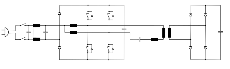
Click image to enlarge
Figure 2: Innovative single-stage topology for a single-phase, galvanically isolated on-board charger
In addition to switching to a new topology with a reduced number of power stages and thus a reduced number of power semiconductor switches, further measures were taken to increase the power density. It exploits all technical advances made possible by using innovative GaN power semiconductors, such as a significant increase in switching frequency compared to established silicon-based power electronics. This makes it possible to reduce the overall installation space or increase the power density, since the passive power components (especially inductors) can also be made more compact by higher-frequency currents. Since the selected circuit topology can switch under ZVS conditions over the entire operating range, the forward losses dominate when considering the total losses in the switching elements. In addition, the losses in the power semiconductors also dominate the total losses over the inductive components and all other loss sources.
Due to the special control of the power semiconductors, with two fast clocking and 180° phase-shifted half bridges, as well as the special control structure to achieve a sinusoidal current consumption, it quickly becomes clear that standard controller ICs can only function insufficiently here. If further improvements of the current characteristics in the zero crossing or a targeted load balancing between the interleave operated half bridges are desired, an application-adapted controller becomes unavoidable. This controller is ideally a fast microcontroller or a DSP with several PWM outputs for direct control of the respective driver circuits of the switching elements.
Finepower