Author:
Silvestro Fimiani, Sr. Product Marketing Manager, Power Integrations
Date
06/30/2022
 PDF
PDF

Click image to enlarge
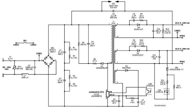
Figure 1: With a properly designed transformer, this flyback power supply continues to operate in the presence of an external magnetic field
Tampering with an electricity meter can be as simple as placing a strong magnet near the power supply transformer. The applied magnetic field can disrupt power conversion and hinder the meter’s ability to accurately monitor electricity usage. Using a magnet to disable an electricity meter is especially effective since it is not detected by commonly implemented anti-tempering schemes. No accurate figures exist to provide an estimate of how much electricity is stolen in this way, but experts believe that it is significant and worth protecting against.
Ferrimagnetics vs. Ferromagnetics
The ferrimagnetic nature of the transformer’s ferrite core (ferrites have crystalline randomly aligned magnetic pole pairs that can spontaneously realign) is the source of the potential for interference and a new transformer design is generally required. Ferrite core materials are used in switched-mode transformers. When exposed to a strong magnetic field, ferrimagnetic materials experience a change in crystalline pole alignment. In a power transformer this can result in a cascading impact on transformer (and power supply) performance:
1. The presence of an external magnetic field causes the internal field intensity in the ferrite core to decrease
2. Flux density β decreases
3. The total magnetic flux decreases, reducing primary inductance
4. If the external magnetic field is strong enough, and the inductance is sufficiently reduced, the power supply will enter auto-restart as switch current ramps to its limit before useful energy transfer can occur. In circuits without a primary current limit, switch failure becomes a real possibility.
Power Integrations has developed a magnetic-interference-proof, dual-output isolated flyback power supply that delivers 16.5 VDC at 300 mA and 16.5 VDC at 100 mA over an input voltage range of 85 to 350 VAC (Figure 1). Design considerations included optimization of the transformer to compensate for the effects of external magnetic fields and component selection and layout.
The design is based on the LNK3696P from the LinkSwitch-XT2 900 V family. The LNK3696P IC supports low component count solutions with an integrated 900 V power MOSFET, oscillator, simple ON/OFF control, a high-voltage switched current source, frequency jittering, cycle-by-cycle current limit and thermal shutdown.
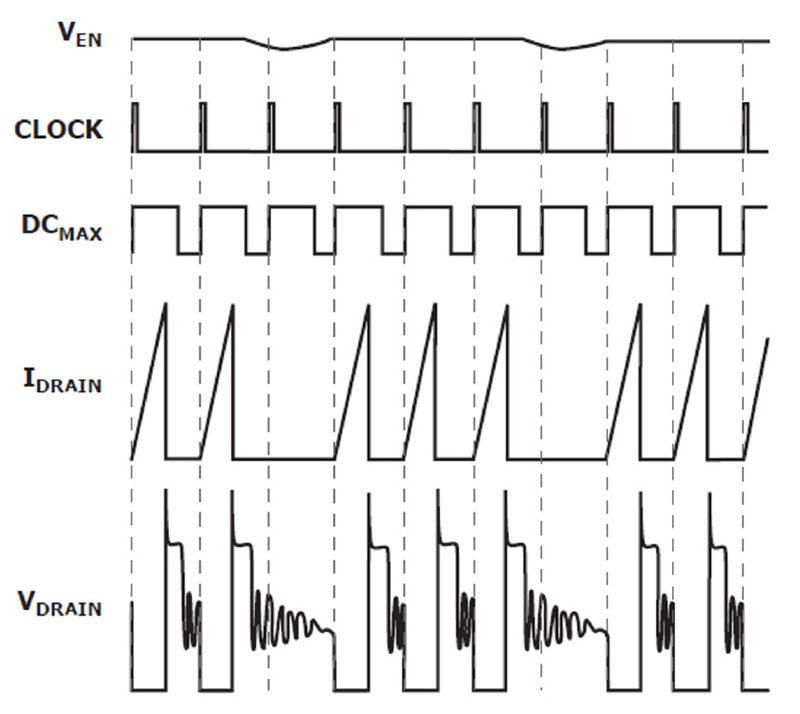
With on-off control the output is examined before each switching cycle. If the output has dropped below a threshold limit, a switching cycle is initiated. If the output is within limits, the switching cycle is skipped. In each switching cycle the switch current is monitored as it ramps, and the switch pulse is terminated when the current exceeds a preset limit. In this way each switching cycle is the same length delivering a fixed packet of energy to the load (Figure 2).
Click image to enlarge
Figure 2: Output power is delivered each time the output voltage drops below a set limit and is measured by the feedback pin (VEN)
In a short circuit, the voltage would stay depressed and energy would be requested every clock cycle. Too many consecutive switching requests would trigger a protective restart that reduces energy to the output.
Because switching only occurs when required, efficiency is higher than a conventional PWM drive at light load. On-off control also does not require loop compensation as it is a non-linear system.
The start-up and operating power are derived directly from the DRAIN pin, eliminating the need for a bias winding and associated circuitry. At 100% load, when a nefarious magnetic field is applied to the transformer of a conventional design, the LinkSwitch-XT2 is forced into auto-restart by the following process:
1. The applied field causes primary inductance to fall by up to 50% of its nominal value (1338 μH)
2. With lower inductance, the core stores less energy during each switching cycle
3. To continue supporting 100% power, the controller adds additional switching cycles to deliver the lower amounts of energy more often
4. A long series of consecutive cycles at full frequency, is interpreted as an output short circuit and a protective auto-restart is initiated. The power supply is unable to switch normally – repeatedly attempting to restart.
To prevent auto-restart in the presence of an external magnetic field, the initial primary inductance needs to double from 1338 μH to 2676 μH. Due to the ferrimagnetic effect described, the application of an external field can reduce the inductance by up to 50% to 1338 μH. With an inductance of 1338 μH, the power supply can start up and support 100% load without entering auto-restart.
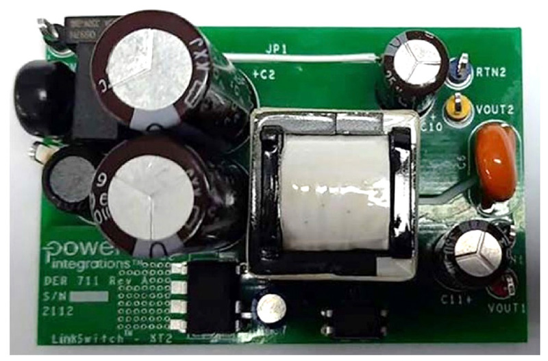
Component selection and placement can also help improve resistance to magnetic interference. To keep any magnet from getting too close to the transformer, tall components such as bulk, Y, and output capacitors, are located around the transformer to create a barrier (Figure 3). The use of a low-profile bobbin also increases the effectiveness of the ‘component barrier.’
Click image to enlarge
Figure 3: DER-711 circuit board showing the placement of ‘tall’ components surrounding the transformer to minimize the proximity of any external magnet
Test setup
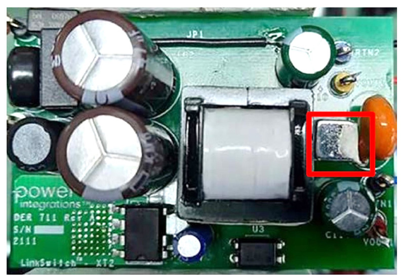
The magnet used during testing can be moved toward the transformer from the side or top. In the test described here, a 6.35 mm square N35 Grade Neodymium Iron Boron (NdFeB) magnet with a strength of 3451 G was placed next to the transformer core to create a ‘worst case’ condition where the primary inductance is reduced by at least 50% (Figure 4). Under this test condition, the power supply was able to start up with 100% load and an input voltage of 75 VAC (also a worst-case condition).
Click image to enlarge
Figure 4. DER-711 PCB as tested with a 3451 G magnet placed directly next to the core (the silver component in the red square)
Test results and performance comparison
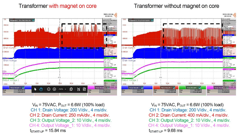
Higher EMI, longer start-up times, lower power conversion efficiency, and the possibility of audible noise are among the considerations when designing an anti-magnetizing interference power supply. Placing a magnet on the core reduces EMI margin for standards compliance, and anti-magnetizing power supply designs require a larger EMI margin. The DER-711 design has >6 dB conducted EMI margin. As noted above, when an external magnetic field is placed near the core, the inductance is decreased, resulting in an increase in switching frequency. There is a corresponding increase in the frequency of the relaxation ringing of the drain voltage. The use of shield windings and proper input filter design are needed to account for the added EMI contributions from the relaxation ringing. In addition to EMI considerations, when a magnet is on the core, the start-up time is longer, increasing from 9.68 ms to 15.84 ms (Figure 5).
Click image to enlarge
Figure 5: In the presence of an external magnetic field, start-up time increases about 6 ms from 9.68 ms to 15.84 ms
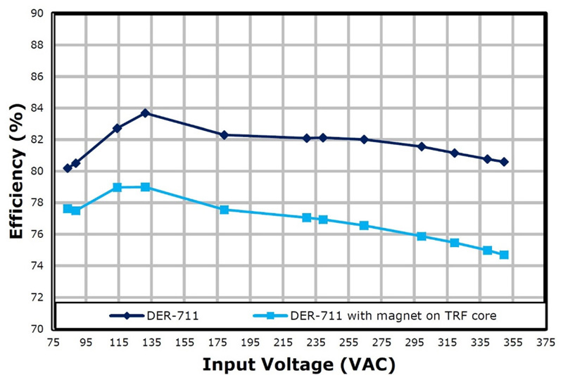
As tested in the extreme case with the magnet directly next to the transformer, the drop in system efficiency is just 4-6% (Figure 6). Under these circumstances, the IC temperature increases by only 16 °C at full load. If the applied magnetic field is lower, the drop in efficiency and the corresponding increase in temperature are both less.
Click image to enlarge
Figure 6: Under worst-case conditions, with the magnet placed next to the transformer, the drop in efficiency is only 4-6%
The maximum magnetic flux density of 2650 G in this design is significantly higher than the recommended maximum of 1500 G for LinkSwitch-XT2 designs. As a result, the switching frequency at full load is reduced and may be low enough to enter the audible range. That is not generally a drawback for power supplies used in electricity meters.
Summary
It is possible to design an anti-magnetizing interference isolated flyback power supply for electricity meters with minimal design tradeoffs. The main consideration is increasing the primary inductance to ensure that the power supply has sufficient headroom to maintain uninterrupted operation at full load in the presence of an external magnetizing interference. Strategic use of a low-profile transformer bobbin and placement of tall components around the transformer to act as a “barrier” and minimize the potential for an external magnet to get near the transformer can also be helpful design considerations.