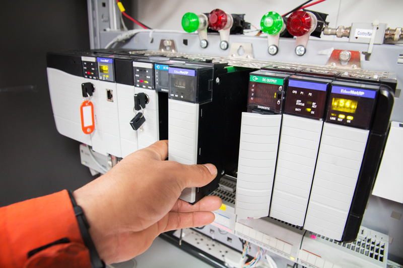
Figure 1. Programmable Logic Controller Module
The vision of the smart factory is a reality in many industries, thanks to advancements in automation and data exchange in manufacturing technologies. Factory floors are filled with controllers, sensors, I/Os, and actuators. A controller can be a programmable logic controller (PLC, Figure 1), motor/motion controller, or a distributed control system (DCS) using advanced processors and microcontrollers. Sensors can be either digital or analog and used for proximity, vision, weight, or temperature. Actuators can be robots, valves, motors, computerized numerical control (CNC), contactors, and other moving mechanisms. Inputs and outputs (I/Os) can be digital or analog or even universal I/Os that connect sensors and actuators to controllers.
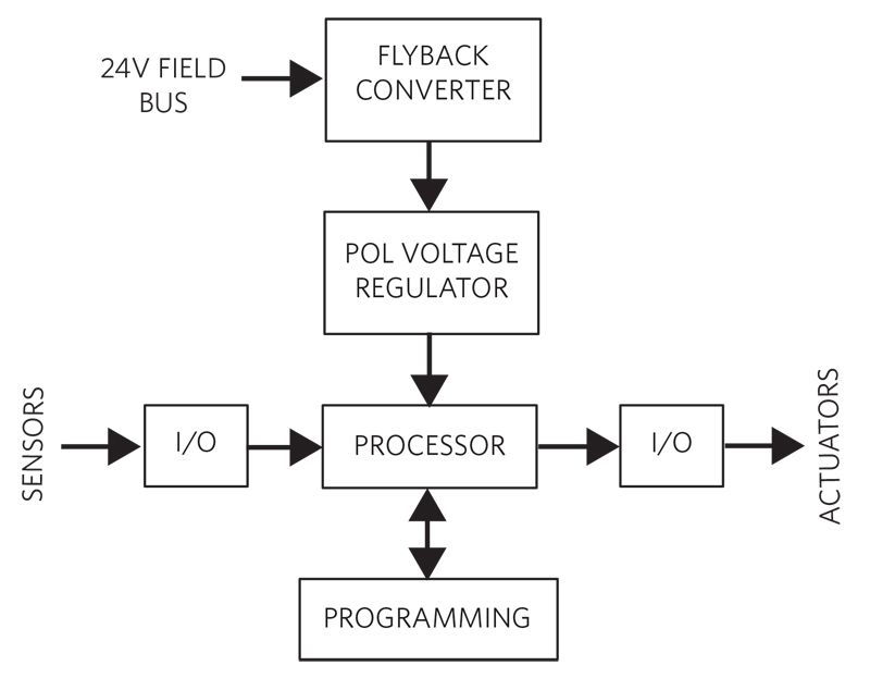
Figure 2 shows a PLC or an industrial computer that monitors and controls a single manufacturing process. It includes a processor, I/O modules, memory/programming, and a power supply. The 24V field bus is bucked down to 5V with the flyback converter, a transformer-based architecture that isolates the PLC module from the harsh industrial electrical environment. The flyback output is converted down to the necessary PLC voltage rail by the POL voltage regulator. PLCs and other control systems are orchestrated by software packages like SCADA (supervisory control and data acquisition), monitoring and controlling multiple interfaces and peripherals.
Click image to enlarge
Figure 2. PLC System Monitors and Controls a Single Manufacturing Process
The PLC receives inputs from sensors on the factory floor, processes them locally, and drives the proper actuators. Today’s sensors, I/Os, and actuators are equipped with internal processors that make simple decisions locally without the need to escalate to the controller, thereby improving throughput. Unless multiple devices need to be considered, the PLC is not even involved. By networking the data generated by all the equipment to the cloud, analytics can be run in real time using advances in AI to determine the action to be taken.
The Challenge
The proliferation of processors and connectivity interfaces into every controller, sensor, I/O, and actuator on the factory floor, places new requirements on system hardware: reduced component size to fit additional electronics in the same chassis, improved energy efficiency to perform within the same or lower thermal budget and increased electrical/mechanical safety and reliability to reduce downtime.
A module approach to the voltage regulator powering the PLC, where the inductor is mounted vertically on top of the IC, reduces the solution BOM, footprint and improves reliability and time-to-market. The voltage regulator module POL, must also be efficient to reduce heat generation, further improving system reliability.
In this design solution, we review a typical module approach to powering the PLC and present a new solution that is cost effective and superior in efficiency and size.
Typical POL Module
A PCB layout for a typical synchronous 5VIN, 1A switching regulator module is shown in Figure 3. The confinement of the inductor results in a reduced footprint of 16.6mm2.
.jpg)
Click image to enlarge
Figure 3. Typical Solution Net Area of 16.6mm2 for a Switching Regulator Module
uSLIC POL Module
The uSLIC module in Figure 4 supports up to 1A load current and allows use of small, low-cost input and output capacitors. A reduced module size (2.6 x 2.1 mm2 vs. 2.6 x 3 mm2).and a reduced BOM (5 components vs. 4 and in a smaller size) results in a cost-effective solution and footprint net area of 11.8mm2 or 29% smaller than the typical solution.
.png)
Click image to enlarge
Figure 4. Improved Solution Net Area 11.8mm2 using a uSLIC POL Module
The output voltage can be adjusted from 0.8V to 3.3V. The module significantly reduces design complexity, manufacturing risks, and offers a true plug-and-play power supply solution, reducing overall time-to-market.
Efficiency Advantage
Figure 5 compares the efficiency of the two solutions. The generic solution (red curve) is ill equipped at light load, where the efficiency drops dramatically, and at full load it falls short of 3% points.
The uSLIC module has high efficiency across the entire range of operation (green curve), making it ideal for line-powered as well as power-stingy battery-powered applications.
.png)
Click image to enlarge
Figure 5. Efficiency Comparison Between the uSLIC Module and Competition
Conclusion
The smart factory relies on a plethora of sensors and actuators placed across the factory floor. The information is processed by PLC modules powered by voltage regulator POLs. A modular approach to the POL reduces system BOM, improves reliability and time-to-market. In this design solution, we reviewed a typical POL and compared it to a novel approach that yields a module that is smaller, has higher efficiency, and is more cost effective.
Maxim Integrated