Programmable DC Loads Support Testing of Large EV Battery Packs
Electric Vehicle designs are pushing power test equipment level every higher
Recent developments in electric vehicle designs are pushing power test equipment levels ever higher. To overcome range anxiety on the part of potential EV buyers, manufacturers are looking to increase battery capacity while at the same time improving electric drive train efficiencies. Both tactics require the need for high power test equipment.
All electrified vehicles rely on rechargeable batteries for their electrical energy source. These batteries must be charged at regular interval using either alternating current or direct current charging technology. AC charging is convenient when drawing power from the utility grid.
Projections
Forecasts on future sales of all electric vehicles are pointing to a growing need for large battery packs. The chart in Figure 1shows demand will continue to increase over the next 25 years. These batteries must be carefully designed and thoroughly tested to meet customer expectations for driving range, durability and above all safety. Without the right tools and equipment, testing of these batteries will be inadequate to meet these goals.

Click image to enlarge
Figure 1: Global EV Sales Forecasts
Charging Standards
Prevailing industry charging standards use a variety for voltage and current ratings such as 120V / 12A, 120V / 16A; 220V / 12A, 220V / 16A, 220V / 80A and others depending on region. For fast public charging stations, three phase power is used to shorten charging times significantly. Often, on-board AC chargers are installed in the vehicle so they can be charged from any available AC outlet although charging times using on-board chargers can be quite long as they are often limited in voltage and current capability. However, ready access to standard grid power is an important convenience.
For DC charging, standards are different by region as well. For Taiwan, Japan and the United State, 600V / 200A are typical. For Europe, 850V / 200A is commonly used while mainland China uses a 750V / 250A three phase DC charging standard. DC fast chargers are typically installed in public charging stations and can offer greatly reduced charging times due to their ability to deliver high voltage and high current at the same time for fast charging of DC batteries.
Battery Charging Methods
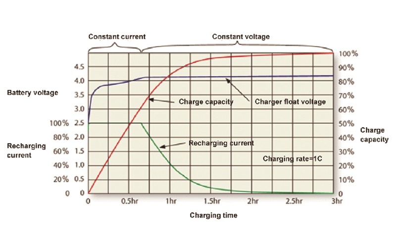
The most common battery charger mode for electric vehicle charging is to use constant current, constant voltage (CC-CV) mode. This means the battery is charged using a constant current level which allows quick charging of the battery while monitoring the battery voltages as it charges up. When the battery voltage reaches its peak voltage, the charger switches over to constant voltage mode preventing the battery voltage from reaching excessive levels. This method is illustrated in Figure 2. Modern electronic DC Loads like the APS 5VP Series support these hybrid battery simulation control modes.
Click image to enlarge
Figure 2: Battery Charging Profile
Electric Vehicle Charging Station Test Methods
When charging electric vehicle batteries using an on-board vehicle charger or charging station, the battery represents a load to the charger. During the charging process, the battery voltage will increase slowly. To enhance the speed of the charger to detect the battery voltage, using an electronic load to simulate a battery and its impedance during charger design will enable better and faster test verification.
For battery simulation applications, the most commonly used Load operating mode is Constant Voltage (CV) which simulates the battery voltage or Constant Resistive mode which simulates the battery impedance.
In Constant Voltage (CV) mode load mode, the terminal voltage of the electronic load is held at the CV setting voltage value. By adjusting the CV setting value, battery states ranging from fully discharged state to fully charged state can be simulated easily.
In Constant Resistive (CR) mode, the terminal voltage of the electronic load is held at the multiple of the charge current and the CR setting value. By changing the CR setting value of the load, various impedance states of the battery can be simulated ranging from fully charged to fully discharged.
As mentioned, Constant Voltage (CV) mode can be used to simulate different state of charge (SoC) conditions of a battery pack during charge and discharge cycles. This include low battery voltage, increasing battery voltage during charging and high voltage state when fully charged. During each stage, the load monitors and displays important parameters such as voltage, power (Watt) and current. At the end of charge cycle, the load will transition to CC mode to CV mode which will be evident from the load display readouts as well. This approach is much more convenient than using actual batteries to test on-board chargers or charging station operation.
Electric Vehicle Battery Test Methods
Once an electric vehicle’s battery is fully charged, it can be driven till almost depleted for maximum driving range. In drive mode, the battery acts as a power source for the electric drive train.
Battery charge and discharge times and associated battery life are important considerations for electric vehicle designs. Another critical design criterion is safe operating area of the battery pack which relates to minimum and maximum charge and discharge voltage levels. For example, a single lithium-ion battery cell’s charging voltage cannot exceed 4.2Vdc to prevent overcharging while the discharge voltage cannot drop below 2.5Vdc to avoid excessive discharge. Both conditions can dramatically affect battery life and quickly and permanently damage the internal structure of the battery cell. Therefore, during development and test, careful attention must be paid to charging and discharging voltage levels to avoid permanent battery damage or deterioration.
Modern electronic DC loads offer special operating modes designed to assist in avoiding conditions during battery discharge testing that could result in permanent battery due to over of under voltage.
1. CC+CV Mode
2. CP+CV Mode
3. CC+UVP Mode
4. CP+UVP Mode
Let’s examine the two most commonly used modes in more detail.
CC+CV Operation Mode
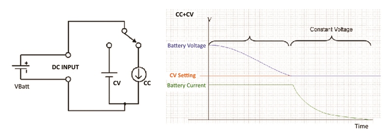
CC+CV mode is aimed at battery discharge testing. In this mode, discharging of the battery starts in CC mode of operation by setting a current discharge level (CC Set point) and a discharge stop voltage level (CV Set point) which determines full state of charge for the battery under test. When the battery voltage drops to the CV set point level, the electronic load stops discharging so that the battery voltage is maintained at the CV set value. Operation in CC+CV mode is very straightforward as the load automatically switches from CC constant current mode discharge mode to CV constant voltage mode. This prevents the battery from being damaged due to excessive discharging. This mode of operation is illustrated in Figure 3.
Click image to enlarge
Figure 3: Battery Discharge using CC+CV Load
CP+CV Operation Mode
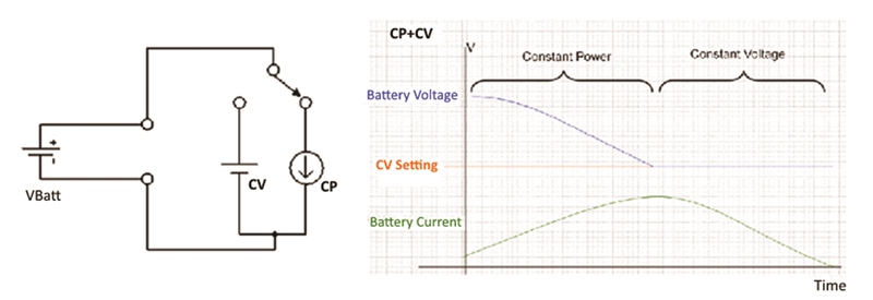
In CC + CP mode of operation, the electronic starts discharging the battery using a constant amount of power drain as determined by the CP set point. Once the battery voltage sags to the CV set point, the load transitions from CP mode to CV mode to maintain the discharged state battery voltage.
Operation in CP+CV mode is very straightforward as the load automatically switches from CP constant power mode discharge mode to CV constant voltage mode. This prevents the battery from being damaged due to excessive discharging. This mode of operation is illustrated in Figure 4.
Click image to enlarge
Figure 4: Battery Discharge using CP+CV Load
Paralleling Loads for Higher Power Requirements
With increasing demand for extended driving range, EV battery packs are increasing in capacity. EV Charger must follow, in particular fast chargers to keep up with the demand to charge these large battery packs as fast as possible. This implies higher voltages and power levels. The APS 5VP Series can be paralleled to increase load size. Up to eight 5VP DC loads can be connected in a master slave configuration.
Configured that way, they act as a single load, all controlled from the master unit. That means only one front panel user interface or one remote control interface to deal with. It also means that current and power measurements are consolidated on the master load so total power and current delivered by the unit under test is available.
To further support discharge testing of large battery packs, the 5VP Series DC loads support built-in discharge profiles so no user programming is needed (although available if needed). This speeds up set up and test system development.
Click image to enlarge
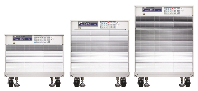
Figure 5: High Power Electronic DC Loads
Conclusion
Increasing demands to extend electric vehicle driving range are putting pressure on engineers to maximize rechargeable battery performance. The right test equipment can support these challenges as it allows rigorous testing of battery performance under a wide range of battery discharge profiles.